• The move to the new server is done. There are some software and database maintenance updates in process. This has us passing the hat around to help out. We appreciate any donations. Seriously, even a dollar helps. The payment page may be found here - https://www.audiokarma.org/support.html

Sherwood S-5000II - No Sound

David_NC

Super Member
I was enjoying the nice afternoon listening to some music in the garage yesterday. A restored Sherwood S-5000II is one sweet amplifier, and it was sounding as good as ever until the sound just sort of fizzled out. There wasn't a pop or smoke or anything dramatic when it stopped, and the amp wasn't being worked hard - average sound levels on efficient speakers. All connections are good, and I turned it off, let it cool, and tried again, just for fun, but no luck.
  • Heaters are working in all tubes
  • I hear only the faintest hum in really efficient speakers with my ear up to the drivers; could this be the output from the drivers?
  • The hum balance switch does nothing, which leads me to believe that the issue is with the output portion of the amp.
Looking at the underside of the amp, I see nothing obviously wrong. I'm not all that familiar with this model, though . It was restored before my getting it, and it has worked flawlessly until yesterday. This is a 7591 model. My tube amp experience is limited to a Dynaco ST-70, and this has far more going on, in terms of components. Due to the fact that both channels are dead, I'm leaning towards (aka guessing) the issue being with the rectifier, though I guess a winding on the transformer could have failed. Still, being that simple things are often the cause, I'd like to rule out some basic things first.
I suppose I should check the voltages on the secondaries first. I can't tell what this model uses for rectification; it's definitely solid state, and my copy of the schematics isn't particularly clear. Other than those two things, I'm fairly clueless as to what could be wrong. Any ideas or suggestions would be appreciated!
 
Register to hide this ad
Definitely sounds like a power supply problem. Without more poking its hard to say for sure what failed but I'd wager its not the transformer. Those honestly don't go bad that often, and when they do its usually the result of abuse, not just random death on a properly working amplifier.

Should be a voltage doubler setup. 2 solid state diodes and a pair of caps. I'd probably check the voltages on the capacitors, fair bet something there will reveal itself. Sherwood schematics are a crapshoot and half of them are not as clear as would be ideal so I know what you mean. Spitballing it, I'd figure the "lower" doubler cap should have about 220v to ground, the "top" one should be closer to 450. First can should also be around 450, and it ought to step down from there. Lowest voltage I'd guess maybe 250v. Mostly we're just looking for someplace that its zero and obviously shouldn't be. I'm hoping its just a bad resistor or bad solder on one of the resistors between supply caps.
 
Definitely sounds like a power supply problem. Without more poking its hard to say for sure what failed but I'd wager its not the transformer. Those honestly don't go bad that often, and when they do its usually the result of abuse, not just random death on a properly working amplifier.

Should be a voltage doubler setup. 2 solid state diodes and a pair of caps. I'd probably check the voltages on the capacitors, fair bet something there will reveal itself. Sherwood schematics are a crapshoot and half of them are not as clear as would be ideal so I know what you mean. Spitballing it, I'd figure the "lower" doubler cap should have about 220v to ground, the "top" one should be closer to 450. First can should also be around 450, and it ought to step down from there. Lowest voltage I'd guess maybe 250v. Mostly we're just looking for someplace that its zero and obviously shouldn't be. I'm hoping its just a bad resistor or bad solder on one of the rebetween supply caps.
I fired it up on a DBT and tested a few things. For some reason, working inside this amp makes me far more nervous than the relatively spartan ST-70. I don't know that the DBT is needed, but it also provides a simple on-off switch. I didn't pay a lot of attention to the voltages, since it was on the DBT, but all did have output, which is good.
Part of what makes this tedious is that the cloth wire colors do not really match up to the schematics. One set of leads goes to a pair of diodes right next to the transformer. A green pair of leads goes to another set of diodes near the front of the amp. From there, it goes to one of the multi-caps. The schematic shows them stopping at two terminals labeled Y and K. Another pair goes to pins 2 and 7 on the output sockets. The schematic does not show these as coming from the transformer. It's almost as if the transformer is not original, but I have no reason to think this is the case otherwise. I don't see anything obvious - loose connections, burned components, etc. I'll poke around and test the various resistance values from sockets to ground and see if they are at least close to what's printed in the manual.
 
probably have 2 sets of diodes. One goes to a cap in the 250v+ range, the other I'd be surprised if its over 100v. The low voltage one is bias and preamp tube heaters, the high voltage one is plate supply. I think the low voltage stuff is closer to the front of the amp.
 
I had a similiar issue with my fisher 800c. Tubes heaters were working so nothing appeared odd tubes were lighting up but no matter what I did there was silence. The 400v going to the power tubes from the SDS power board had a cold soldier.
 
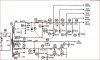
Here's the Sams, which can be enlarged to show detail. Note that Sherwood often made running changes during production so there may be some differences.
Thanks for that; it's much more legible and will def. help.
Looks like I need to do some more checking around. I'll test points for the correct voltages.
 
gonna take a wild guess and say the problem will be at the 33 ohm resistor between C1 and C2B but thats purely a guess.
 
gonna take a wild guess and say the problem will be at the 33 ohm resistor between C1 and C2B but thats purely a guess.
That's the one in the upper right of the red 'circle', I believe (R102):
Capture.JPG
If only the insulation was the colors shown here! This should be just past the set of diodes near the transformer and the outputs, so that'll help me find it. Thanks!
 
From your initial description, it does sound like you lost the B+ plate voltage supply. The heater supply is totally separate so the tubes will stay lit but the plates won't have the high voltage needed for them to work.

Yes, check R102. Should be connected to the can C1 and should look like a white or sandy looking square block. They can also be round and darker color but they will look bigger than all the other resistors.

Take a meter to before and after that resistor. If you get voltage before but none after, there's your problem.
 
Last edited:
Back
Top Bottom