• The move to the new server is done. There are some software and database maintenance updates in process. This has us passing the hat around to help out. We appreciate any donations. Seriously, even a dollar helps. The payment page may be found here - https://www.audiokarma.org/support.html

Sherwood SEL-200 Transistors - Help Please!

nabeelsayegh

AK Subscriber
Subscriber
Moderator's note: the original poster here has some info on what worked and what did not... after a year of testing... which can be found a little further down in the thread. You may want to read this post before taking any advice found here.

Good evening AK...

I have been scouring the web trying to find any information about verified/credible replacement parts for the power output transistors on this receiver as well as a few others. Not being able to search AK is truly debilitating so bear with me if there is something in here that covers this already. The power outputs are listed only as "S200". They are RCA branded, but that is about all I am coming up with. Some folks reference that you can use a 2N3055, others say NTE87 and I think i even saw reference to an MJ15024G and MJ21194G (but neither are available). Well, i am not all that keen into guessing so if there are any Sherwood pros out here, any help would be GREATLY appreciated.

The unit I am working on has one channel severely damaged and the other seem to have had some misc transistors replaced as well. I need to rebuild the blown channel completely so i am after the following (Note: this list is based on the serial number of the unit i have as there does seem to be some variation on what was installed based on early, mid and late version releases of this model.)

Tone Control
Q201 - S169N/BC169N - KSC1845
Q202 - S169N/BC169N - KSC1845
Q203 - S169/BC169 - KSC1845
Q204 - S169/BC169 - KSC1845

Amp Driver
Q205 - S169/BC169 - KSC1845
Q206 - SPS41V - BC546A
Q207 - SPS4199 - MPSA06
Q208 - S169/BC169 - KSC1845
Q209 - S2104 - NTE128
Q210 - S522 - NTE129
Q211 - S409F - 2N3439
Q212 - S409F - 2N3439
Q213 - S200 - ???
Q214 - S200 - ???
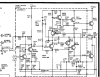
Screenshot 2023-06-07 183011.png
 
Last edited by a moderator:
Register to hide this ad
I looked briefly at the 2N3055 datasheet and it looks pretty similar to 2SD180's that were in my Sansui AU-555 (20 WPC rated but puts out about 25). I replaced them with 2N3773G, which I got recently from Mouser and they seem to work well. I'm not that experienced at coming up with transistor substitutions and someone more experienced might have a better idea.
https://www.mouser.com/datasheet/2/308/2N3773_D-2309454.pdf
 
While MJ21196 a rated higher than what you need, they should work fine. Dont use 2N3055 as the voltage rating on them is too low (only 60V).
 
MJ21196 doesn't seem to be available right now though at least from Mouser and DigiKey. 2N3773G are available and they look like they'd handle more than the 75V shown in the schematic.
 
It looks like Digikey has a bunch of them in stock so i will give them a go and report back. thank you guys so much!
 
So, I circled back to this project now that i got all the parts in. I built these channels and did an initial startup on a DBT. No smoke or bright lights...which is a good thing. BUT....i am getting no sound. When it turns on, i do get a turn on thump followed by hum in both channels which dies down. The hum is still there, but no output at all. I have double and triple checked components to make sure everything is in the right spot and that they are oriented correctly using the schematic as a reference. One thing that is standing out to me is that my voltages are way off. Power supplies are at the correct level feeding the driver board (39V and 75V...actually, it's about 35V and 68V...but close enough)....BUT the schematic clearly states that i should be getting about 33V on the output transistor facing side of the output coupling caps. Well, i am not. I have pulled the driver transistors and power output transistors and I still see this voltage present. So I decided to put back in the original driver/small signal transistors....and still nothing.

This to note: The caps were replaced with Nichicon 22uf (instead of 20uF) axials, the output coupling caps were replaced with Nichicon 4700uF (instead of 4,000uf) and the main filter cap was replaced with the 6800uf instead of the 6,000. Pretty sure these variances would not be causing my problem. Making adjustments to the pots on the driver board make no difference (and i cannot find a procedure to do a bias adjustment/alignment.) So at this point, I am kind of dead in the water. Any idea what I should check next?
 
Ok...never mind; I screwed up!

I apparently did miss one transistor in the overload section (on both channels). Had the pin orientation back-asswards. She fired right up after correcting this. I did have some erratic behavior until I reset the output balance to back down the center point voltage from what was running at almost 45V down to the 33V that the schematic called for. Adjusted bias control until i got 0.55V. So far, so good. Going to run her for a while now and re-validate voltages/bias to check for any drift. Pics to follow.
 
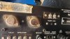
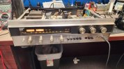
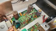
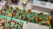
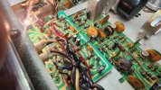
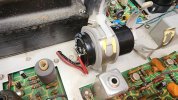
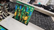
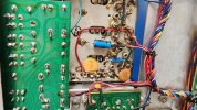
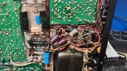
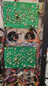
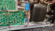
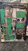
Here are some pics of the unit up close and personal. Note: I am going to come up with a 3D printed mount for the new main filter cap.....dont worry...i am not planning to leave it zip tied in place.....even though I did actually think about it....LOL.
 

Attachments

  • 20230709_185821.jpg
    20230709_185821.jpg
    105.7 KB · Views: 17
  • 20230709_185830.jpg
    20230709_185830.jpg
    143.2 KB · Views: 16
  • 20230709_185837.jpg
    20230709_185837.jpg
    140.2 KB · Views: 14
  • 20230709_185844.jpg
    20230709_185844.jpg
    140.1 KB · Views: 14
  • 20230709_185849.jpg
    20230709_185849.jpg
    143.3 KB · Views: 11
  • 20230709_185902.jpg
    20230709_185902.jpg
    142.3 KB · Views: 12
  • 20230709_185909.jpg
    20230709_185909.jpg
    131.4 KB · Views: 13
  • 20230709_185923.jpg
    20230709_185923.jpg
    139.5 KB · Views: 13
  • 20230709_185938.jpg
    20230709_185938.jpg
    175.9 KB · Views: 16
Here's a few more....
 

Attachments

  • 20230709_185942.jpg
    20230709_185942.jpg
    137.7 KB · Views: 2
  • 20230709_185951.jpg
    20230709_185951.jpg
    155.9 KB · Views: 2
  • 20230709_185958.jpg
    20230709_185958.jpg
    158.2 KB · Views: 2
  • 20230709_190003.jpg
    20230709_190003.jpg
    152.3 KB · Views: 2
By the way, all the replacement transistors noted above all seem to be working just fine including the use of the MJ21196 in place of the original RCA S200's.
 
So just an update on this unit... I have it up and running, BUT....just in case anyone needs to replace the ouputs...DO NOT use MJ21194/96. Also the MJ150xx do not work either. Come to find out that these throw the unit into oscillation and as soon as you give it signal, it starts to lose it's mind. I was extremely fortunate to find a junk unit that still had a pair of good S200 transistors and using them along with another good pair I, the unit worked perfectly....just by swapping out the power outputs with the original ones. There was a write up about a similar unit (the S8800) that Audiorehab mentions the use of NEC 2SD555 or Sony 2SD45 or 2SD88. I acquired a set of the 2SD555 and I am going to try them out and verify if they work as replacements or not. Will report back for everyone's benefit.
 
oops...forgot to report back. The 2SD45's did seem to work ok....but I kept the S200's in there for obvious reasons. I will most likely use the 2SD45s on the donor unit I got when I have free time to rebuild it. (Did I just say free time????)
 
Back
Top Bottom