
• The move to the new server is done. There are some software and database maintenance updates in process. This has us passing the hat around to help out. We appreciate any donations. Seriously, even a dollar helps. The payment page may be found here - https://www.audiokarma.org/support.html

Signal Generator Level/Output

reverend13

AK Subscriber
Subscriber
Greetings everyone!

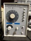
I did a search and couldn’t find an answer to what may be a silly question. I have the attached signal generator and using an oscilloscope to test the outputs of a solid state receiver to measure where it starts to clip.

On the signal generator, how far up do I need the attenuator and/or amplitude to pass the signal through the receiver’s aux inputs? How much is too much? I’m assuming from there I would increase the receiver’s volume up to clipping to measure on the oscilloscope?

Thanks for everyone’s help.
IMG_3374.jpeg
 
Register to hide this ad
the receiver's service manual will state the input level required to achieve maximum power.

usually somewhere around 150mv into aux. with cable loss that could be 200mv.

then like you said, use the receiver's volume control to bring up the output
 
the receiver's service manual will state the input level required to achieve maximum power.

usually somewhere around 150mv into aux. with cable loss that could be 200mv.

then like you said, use the receiver's volume control to bring up the output
Thanks. It’s for a Marantz 2216 and found the aux input should be 150mv (not taking into consideration the cable’s resistance). I couldn’t find it in the service manual but did a search. Thanks again.
 
Greetings everyone!

I did a search and couldn’t find an answer to what may be a silly question. I have the attached signal generator and using an oscilloscope to test the outputs of a solid state receiver to measure where it starts to clip.

On the signal generator, how far up do I need the attenuator and/or amplitude to pass the signal through the receiver’s aux inputs? How much is too much? I’m assuming from there I would increase the receiver’s volume up to clipping to measure on the oscilloscope?

Thanks for everyone’s help.

View attachment 3164587
Give that TAG 101 about 20 minutes to stabilize before using it.
That's about how long mine takes. If your scope shows the frequency use it to dial in the 1KH signal. The dial on the 101 is a bit off.
 
The old rule of thumb, is to turn the audio generator`s output to the lowest setting, connect it to the desired device`s audio input, turn all tone/loudness controls to their flat position if present, or disable/bypass them via switch, if that function is available.
Turn the to be power tested audio component on, advance it`s volume control to it`s maximum setting, then start advancing the audio generator`s output course attenuator(s) slowly while observing the scope`s display until the waveform just starts to flatten the top and bottom of peaks of the displayed sine wave form, then back off slightly the audio generator`s output using any fine attenuator/variable control adjustments available until no apparent sine wave peaks flattening is observed.

At that point that should indicate the amplifier`s maximum as visually apparent on the scope clean power for the specific ohmic dummy load that is connected to it.
 
Give that TAG 101 about 20 minutes to stabilize before using it.
That's about how long mine takes. If your scope shows the frequency use it to dial in the 1KH signal. The dial on the 101 is a bit off.

Yeah, the dial ended up being about 100 Hz off of 1kHZ, so thanks for the call-out on this. It is touchy trying to get the signal to 150mv, so will follow this....
The old rule of thumb, is to turn the audio generator`s output to the lowest setting, connect it to the desired device`s audio input, turn all tone/loudness controls to their flat position if present, or disable/bypass them via switch, if that function is available.
Turn the to be power tested audio component on, advance it`s volume control to it`s maximum setting, then start advancing the audio generator`s output course attenuator(s) slowly while observing the scope`s display until the waveform just starts to flatten the top and bottom of peaks of the displayed sine wave form, then back off slightly the audio generator`s output using any fine attenuator/variable control adjustments available until no apparent sine wave peaks flattening is observed.

At that point that should indicate the amplifier`s maximum as visually apparent on the scope clean power for the specific ohmic dummy load that is connected to it.
Which brings up a dumb question on my part using either approach..... For measuring input signal though aux or at output, am I using Peak or RMS?

Thanks,
 
Yeah, the dial ended up being about 100 Hz off of 1kHZ, so thanks for the call-out on this. It is touchy trying to get the signal to 150mv, so will follow this....

Which brings up a dumb question on my part using either approach..... For measuring input signal though aux or at output, am I using Peak or RMS?

Thanks,
Generally RMS is measured, via a decent quality analog or digital readout meter, that is capable of measuring accurately voltages across the full audio bandwidth (20 ~20khz), and not just at AC power frequencies like 50/60, or 400 Hz like lessor meters usually only do.
 
Back
Top Bottom