
• The move to the new server is done. There are some software and database maintenance updates in process. This has us passing the hat around to help out. We appreciate any donations. Seriously, even a dollar helps. The payment page may be found here - https://www.audiokarma.org/support.html

Simple XO Question

anotherhobby

Active Member
Or Two -

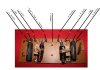
XO Re-Purposed from a Magnavox Console Astro-Sonic / Re-Purpose the Woofer and Horn also ....

I want to ty to build a set of XO identical to these with new parts, my first go at XO building, figure copy what works ....

Questions are:
1) The white resistor is a 4.7 Ohm / how do I determine the watts?
2) The inductor is an Iron Core type, how do I determine the mH Value?
3) Where can I source the male spade term on the XO

XO Wiring Question:
1) Where do I tie the - from the amp to the XO / would it go next to the woofer - on the open spade?

Thanks for any advice or answers
 

Attachments

  • XO description.jpg
    XO description.jpg
    46.1 KB · Views: 63
Register to hide this ad
Questions are:
1) The white resistor is a 4.7 Ohm / how do I determine the watts?
2) The inductor is an Iron Core type, how do I determine the mH Value?
3) Where can I source the male spade term on the XO

1) It's usually marked on that type of resistor. I'll guess 5w.
2) An LC Meter. Here's a link to a DIY LC meter. http://my.integritynet.com.au/purdic/lc-meter-project.htm . If you have something like Woofer Tester from Parts Express, it will measure inductors as well.
3) Digi-Key or any other worthwhile parts place http://parts.digikey.com/1/parts-kws/faston-terminal-tab-male They are known as male disconnects - pc mount.

If all you are doing is reusing the XO with the existing drivers, there's not much point in changing the resistor or the inductor. Those parts are likely just fine. Change out the Cap is really all you need to do. Also Those drivers are going to like an enclosure similar to whatever they were in previously... ie in very simple terms if it's a big open back then that's what they want, if it's a sealed enclosure (unlikely) then that's what they want.

If you are repurposing the XO for a different set of drivers, I'd say don't bother. That existing XO was likely designed to match the existing drivers cutoff and impedance. Best maybe to start from scratch if you want a new XO for a new set of speakers.
 
Thanks, I searched every word I could think of for the male tabs, except "tab" / "pc-mount" ....

Yes this XO will be used with the same drivers / I have read that I can only replace the cap and thats all really needs done. However I dont want to destroy this one and rebuild some identical / seperate and a little better looking

These drivers will going in an open baffle design, figure it may work as the console was very open / non sealed etc ...

any ideas on the "singal path" from the amp in bindings to the XO ?

Thanks for the links / the DIY LC Meter is way out of my skill set ...
 
I think the signal path is OK as it is now. In this way, you have a second order xover to the horn (a cap in series with the horn, a coil in parallel with the horn. A Resistor in series with the cap to attenuate the signal), and a full range woofer (nothing between the woofer and the amp).

If the resistor is between the amp and the capacitor, it doesn't modify the impedance seen by the xover, but between the capacitor and the horn, it's part of the impedance seen by the xover, so the result is not the same. You can modify the crossover point plugging it in the wrong way.

The "-" jumper is just a common ground to all the circuit, so plugging the "-" from the amp in any of this spades will be the same.

Regarding the coil value:

Using this on line calculator: http://www.bcae1.com/xoorder.htm

looking at your 8uF cap, and GUESSING the impedance of your drivers, I can deduce this:

An 8uF capacitor could work with in this way:

with an 8.2 mH coil, with a 16 ohm driver, to give a xover point of 620 Hz

with a 2.1 mH coil, with an 8 ohm driver, to give a xover point of 1200 Hz

with a 5.44mH coil, with a 13 ohm load (8 ohm driver + 5 ohm resistance...), to give a xover point of 760 Hz

So... you need to know the impedance of your horn... or take the coil to an electronics shop and ask to measure it :)

I've seen that old horns usually cross at 800 Hz.
 
The horn is 16 Ohms / Woofer is 8 Ohms

So I can connect the - from amp to the open spade next to the - woofer on both left and right ?


I think the signal path is OK as it is now. In this way, you have a second order xover to the horn (a cap in series with the horn, a coil in parallel with the horn. A Resistor in series with the cap to attenuate the signal), and a full range woofer (nothing between the woofer and the amp).

If the resistor is between the amp and the capacitor, it doesn't modify the impedance seen by the xover, but between the capacitor and the horn, it's part of the impedance seen by the xover, so the result is not the same. You can modify the crossover point plugging it in the wrong way.

The "-" jumper is just a common ground to all the circuit, so plugging the "-" from the amp in any of this spades will be the same.

Regarding the coil value:

Using this on line calculator: http://www.bcae1.com/xoorder.htm

looking at your 8uF cap, and GUESSING the impedance of your drivers, I can deduce this:

An 8uF capacitor could work with in this way:

with an 8.2 mH coil, with a 16 ohm driver, to give a xover point of 620 Hz

with a 2.1 mH coil, with an 8 ohm driver, to give a xover point of 1200 Hz

with a 5.44mH coil, with a 13 ohm load (8 ohm driver + 5 ohm resistance...), to give a xover point of 760 Hz

So... you need to know the impedance of your horn... or take the coil to an electronics shop and ask to measure it :)

I've seen that old horns usually cross at 800 Hz.
 
You can connect the "-" from the amp, to the "-" spades next to the "-" jumper.

If you have Left "-" and Right "-", you don't need that jumper , better keep the Right and Left circuits separated, remove the jumper, just plug each channel in their own xover.

Regarding the inductor, if the horn is 16 ohm, an 8.2 (or 8) mH coil makes sense. It gives a 620 Hz xover point with your 8uF cap, quite usual for that old horn.

But that resistor in series with the capacitor, in theory, would be lowering the crossover point to 480Hz... quite low to that kind of driver. if you are building a new crossover, I would try the resistor BEFORE the capacitor, between the amp signal and the cap. You can give it a try, and change it later if you you want.
 
Back
Top Bottom