• The move to the new server is done. There are some software and database maintenance updates in process. This has us passing the hat around to help out. We appreciate any donations. Seriously, even a dollar helps. The payment page may be found here - https://www.audiokarma.org/support.html

Single resistor in series db loss?

flyingfinn

New Member
Greeting all. I have an 8ohm mid of which I'm looking to build an 800hz-2900hz 1st order band pass. I have what I need on hand, but only if I add a 4 ohm resistor to make it 12ohm. If I do this, approximately how much db will I lose? The only charts that i can find is for fixed L-pads. Thanks!
 
Register to hide this ad
When you say "build an 800Hz-2900Hz 1st order bandpass", do you mean a crossover? Is that a ready-made general purpose crossover?
In general, if you add a 4 Ohm resistor in series with an 8Ohm speaker driver, 1/3 of the power would be dissipated by that resistor. In addition to losing a lot of signal, you would be generating an awful lot of heat on that resistor and it would also need to be rated at at least 1/3 wattage as the power sent to the driver. Not a viable solution. The resistor would need to be large and inside the loudspeaker it would create a heat source that can also be catastrophic (cause a fire).

In loudspeaker crossovers, I have never seen a series resistor to a woofer or midrange. You may get a series resistor for the tweeter, if it's too sensitive to match the rest of the drivers.
 
When you say "build an 800Hz-2900Hz 1st order bandpass", do you mean a crossover? Is that a ready-made general purpose crossover?
In general, if you add a 4 Ohm resistor in series with an 8Ohm speaker driver, 1/3 of the power would be dissipated by that resistor. In addition to losing a lot of signal, you would be generating an awful lot of heat on that resistor and it would also need to be rated at at least 1/3 wattage as the power sent to the driver. Not a viable solution. The resistor would need to be large and inside the loudspeaker it would create a heat source that can also be catastrophic (cause a fire).

In loudspeaker crossovers, I have never seen a series resistor to a woofer or midrange. You may get a series resistor for the tweeter, if it's too sensitive to match the rest of the drivers.

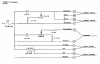
Yes. The bandpass crossover I wold like to build is for my Infinity Column II. I've uploaded a schematic of the original xo which doesn't work. It does have resistors in the midrange section. I've been temporarily using a cheap 800-5000hz ready-made PE bandpass. The tweets are crossed at 6khz, so I have a bump in the upper mid. At 12ohm, an 800hz-2900hz bandpass xo is exactly a 12uF cap, and a 0.9mH coil.

I know simple math says that 4 is one third of 12, but how many decibels does that translate to?
 

Attachments

  • infinity-column-II-schematic.png
    infinity-column-II-schematic.png
    120.2 KB · Views: 20
A 3dB drop is half the volume, so you can work with that. Increasing the resistance by 1/3 would give somewhere around 2dB drop.
If you put the series resistor after the bandpass section, you would be eliminating most of the non-needed signal. The 5W rating of the adjustment pot in the original crossover is an indication of the power rating you need. I would go safer and put there a10W resistor.
 
Why don't you fix the original crossover? You should duplicate the original circuit to make the speaker work properly.

The original crossover has 2 resistors, one 5ohm potentiometer (variable voltage divider) and a fixed resistor. You could "simulate" the mid position of that attenuator using 2 fixed resistors. you could use something close to 2.5ohm, or a 2 ohm and a 3.3 ohm, choosing at which side you want the 3 ohm, and which side the 2 ohm. I guess you can use the original 9.4 ohm resistor if you still have it. One or 2 tenths of an ohm won't make a difference in this application.

Forget about online crossover calculators and xover points. If you are using the original midrange driver, copy the original crossover values.
 
db = 20log (v1/v2)
a 4 ohm resistor in series with 8 ohms will account for 1/3 of the total voltage, so 2/3 remains across the tweeter
so lets assume 3 volts, just because it makes the math easier. This will come out the same no matter what the specific voltages are so long as the ratios match but round numbers are less annoying
V1 = voltage across the tweeter with the resistor
V2 = total voltage

so 20log (2/3) = -3.5 db, so with the resistor you will be 3.5 db down from where it was previously.
 
Why don't you fix the original crossover? You should duplicate the original circuit to make the speaker work properly.

The original crossover has 2 resistors, one 5ohm potentiometer (variable voltage divider) and a fixed resistor. You could "simulate" the mid position of that attenuator using 2 fixed resistors. you could use something close to 2.5ohm, or a 2 ohm and a 3.3 ohm, choosing at which side you want the 3 ohm, and which side the 2 ohm. I guess you can use the original 9.4 ohm resistor if you still have it. One or 2 tenths of an ohm won't make a difference in this application.

Forget about online crossover calculators and xover points. If you are using the original midrange driver, copy the original crossover values.

Restoring the original xo with upgraded caps is now my long term plan. It's stapled in place, so I'm a little leery removing it without damaging anything. Also, I would like to keep the potentiometers for flexibility. 5ohm ones don't exist anymore. So, I figured a solution would be to eliminate the fixed resistors, and just use 8ohm potentiometers. I could be wrong, but you should be able to get the sound level you want from the mids and tweets since pots are adjustable. You would just need adjust the cap and coil values to maintain Infinity's original crossover points.

It has been a long journey. When I bought these speakers, the original woofs were long gone, and replaced with $17 Goldwood's from PE. According to Infinity's original literature, the forward firing woof was designed to act as a midwoofer, and the downward firing one was doped to act as a sub. Since the OE drivers are nonexistent, I put a decent 4-ohm sub in the bottom, use the original 4.3 mH coil to cross it over way low. Then, install a PRV 10MB400 on the front, crossing it over with a ready-made PE 800hz 2nd order butterworth low pass from PE. Unfortunately, the PRV's 97db SPL was still way too much. Then, one of the original mids blew, and the mid section of the original xo also quit working. So, I decided to "upgrade" bought a pair of dome mids from Mavin, crossing them over with a 1st order PE 800hz-5khz bandpass. Their performance was meh, they drowned out the highs. So I then put some more efficient palnar (similar to HiVi RT1C-A but 8 ohm instead of 6) to compensate. Still sounded terrible.

It was only then that I FINALLY made the correct decision to get things back to as original as possible. So, started by purchasing a pair of the OE Phillips mids. Top tip: They are all 8ohm even though most of them were used in 4ohm Infinity designs. If I had known that, I would have NEVER tried to replace them with something different. I then paralleled the 2 woofs into the original 4.3mH coil, which creates a 6ohm load, and crosses them over at 225hz. That seems to tamed the PRV, and fixed the woof/mid relationship. However, I can't tell for sure because the upper mid is so loud. Building my proposed bandpass should give me the data that I need. Since I don't have and can't get the original woofers, rebuilding the original xo to the exact factory spec might not be what's best. A little trial and error is needed to figure a few things out.

This may have been a long-winded explanation. I hope someone facing a similar situation will read this, not make the same mistakes, and spare themselves from the frustration that I experienced.

 
Last edited:
I see. You are designing a whole new speaker with new drivers. I think , if you are taking all this long way, you should buy a microphone and do some measurements. It will shorten the way to a successful design. You will actually see the freq response, the crossover points, the changes made when you replace a component. You will see exactly what's happening, how the different drivers interact, and you'll see that the freq response graphs are -in many cases- quite far from what a crossover calculator says.
 
I see. You are designing a whole new speaker with new drivers. I think , if you are taking all this long way, you should buy a microphone and do some measurements. It will shorten the way to a successful design. You will actually see the freq response, the crossover points, the changes made when you replace a component. You will see exactly what's happening, how the different drivers interact, and you'll see that the freq response graphs are -in many cases- quite far from what a crossover calculator says.

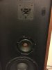
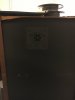
Actually, I'm still using the Infinity mids and piezo tweets. I just to need figure out how to make them work with the aftermarket woofers since the originals aren't available. The mids with the octogonal frame which Infinity used throughout the late 70's and early 80's are actually made in Belgium by Phillips. As far as the tweets go, Infinity seemed to a lot of experimenting before developing their signature EMIT ribbon tweeter. These column II's have 2 piezo tweeters (one front, one back), but oddly, the don't have ANY horn/waveguide.
 

Attachments

  • IMG_3536.JPG
    IMG_3536.JPG
    98 KB · Views: 13
  • IMG_3537.JPG
    IMG_3537.JPG
    42.4 KB · Views: 11
Actually, I'm still using the Infinity mids and piezo tweets. I just to need figure out how to make them work with the aftermarket woofers since the originals aren't available. The mids with the octogonal frame which Infinity used throughout the late 70's and early 80's are actually made in Belgium by Phillips. As far as the tweets go, Infinity seemed to a lot of experimenting before developing their signature EMIT ribbon tweeter. These column II's have 2 piezo tweeters (one front, one back), but oddly, the don't have ANY horn/waveguide.

Well, if you have the original mids and tweeters, what I'd do is to keep the original crossover design for the mid and tweeter, and start to tweak or redesign the bass section crossover.

The Philips mid came in 4 and 8 ohm versions. I assume you already checked that your model used the 8 ohm version. I know those Philips mids , I have them in my infinity Qb and I have another pair for another Qbs I'm building from scratch.

In any case, I'd try to get a microphone and start measuring what's happening.
 
Back
Top Bottom