


David_NC
Super Member
Over the weekend, we were enjoying some music in the back yard. I was using my recently restored Pioneer ER-420 tube receiver. As we were winding down, I heard a small pop, and the GFCI tripped. It would trip whenever I plugged in the receiver - on or off - and had it connected to a cheap USB DAC connected to a PC. My multimeter showed full line voltage between the RCA jacks on the DAC and the receiver's chassis.
Opening it up didn't show anything, but clues indicated it was the transformer or switch / wiring. In this model, the power switch is enclosed in a heavy steel 'box' that's accessed by removing the front panel. Thinking that the switch or wiring had perhaps shorted, I started there. Here's what I found:
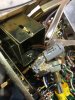
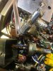
Besides being hidden from view, this cap wasn't really documented in the manual. Still, this serves as a warning to those with 50+ year old PIO caps. It was rated at 400 volts, but 120 was too much for it, these days. So, I need to install a new snubber. It doesn't have to be 400 volts; that cap is similar to the dozens of caps that were replaced, so I'm assuming they used a part on hand vs a specific cap for this purpose.
How would these work for this purpose:
https://www.amazon.com/dp/B07QXZLXV...colid=X6KL6NN4353O&psc=1&ref_=lv_ov_lig_dp_it
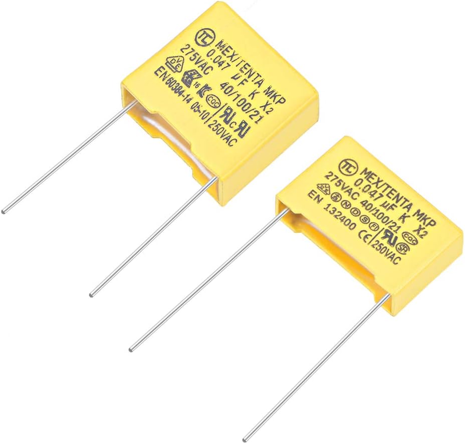
.047uF is fine for the original .05uF, and all that I see are rated at 275 V, and I'd think that'd be fine, too. I've read that a resistor should be installed in series; if so, what type and value should I use? Thanks for any advice or ideas on this.
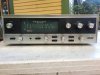
Here's the receiver in question, if anybody was curious:
Opening it up didn't show anything, but clues indicated it was the transformer or switch / wiring. In this model, the power switch is enclosed in a heavy steel 'box' that's accessed by removing the front panel. Thinking that the switch or wiring had perhaps shorted, I started there. Here's what I found:
Besides being hidden from view, this cap wasn't really documented in the manual. Still, this serves as a warning to those with 50+ year old PIO caps. It was rated at 400 volts, but 120 was too much for it, these days. So, I need to install a new snubber. It doesn't have to be 400 volts; that cap is similar to the dozens of caps that were replaced, so I'm assuming they used a part on hand vs a specific cap for this purpose.
How would these work for this purpose:
https://www.amazon.com/dp/B07QXZLXV...colid=X6KL6NN4353O&psc=1&ref_=lv_ov_lig_dp_it
.047uF is fine for the original .05uF, and all that I see are rated at 275 V, and I'd think that'd be fine, too. I've read that a resistor should be installed in series; if so, what type and value should I use? Thanks for any advice or ideas on this.
Here's the receiver in question, if anybody was curious:


