• The move to the new server is done. There are some software and database maintenance updates in process. This has us passing the hat around to help out. We appreciate any donations. Seriously, even a dollar helps. The payment page may be found here - https://www.audiokarma.org/support.html

So I picked up a Yamaha CR1020 - no relay click

bhairavi

AK Subscriber
Subscriber
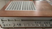
WhatsApp Image 2024-07-15 at 10.46.07 PM.jpeg

This thing is beastly! And gorgeous. Seller says that last he checked a few weeks ago it was fully functional (and I believe him). He bought off reverb around 2019 so hasn't been serviced at least since then. Has been serviced at some point because the VU meter lights are green (yuck) and the radio dial light is yellow.

Given that @mbz is currently helping me with a CA1000 I thought I'd apply what I've learned and start with DBT. 100w DBT no light at all, 40w DBT dim. Off of DBT, no smell no smoke, but still no relay click.

WhatsApp Image 2024-07-15 at 10.33.17 PM.jpeg

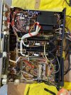
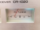
First thing I noticed when I opened up the case was that this seems much more difficult to work on than the ca1000. After I blew out the dust I looked and felt around, and noted that the two heatsinked transistors on the power board seemed pretty loose. Long story short, I believe these might be the culprit as there is a thread on AK discussing this exact issue, @ivandezande also mentions this here, and one of the telltale signs is that the FM tuning meter is stuck at -50. I don't know why they're called 'pass transistors'.
WhatsApp Image 2024-07-15 at 10.32.45 PM.jpeg

I'll try to reflow the solder to these and see if that fixes it, if not I'll take them out of the circuit and test them. Also hoping that I don't have broken traces. TR712,5 are 2SD234R, and replacements per an old merrylander comment is TIP31AG.

I suppose I'm banking on being lucky and on this being the real reason it's stuck in protection. Also I have my hands full with the CA, and if this CR requires a lot more/complex troubleshooting, then it'll have to wait until I'm done with the CA.


I did do a little bit of legwork and made the following measurements:

On the power circuit:
ground to L1 30mv
ground to R1 60mv

On the main circuits:
+/-B are +/- 44v
TP1-0 is L 3.2 mv / R 3mv - these were adjusted to 10mv
ground (speaker out) to TP0 is L 70mv / R 30mv

Also jiggled the switches including the coupler, but I didn't think that'd be the issue since no relay click.

All 6 fuses (5x 5A, 1x 1A) are functional.


Just putting this here so I can refer back to it:
Merrylander said: There are six fuses in the 1020, two 5A on each power amplifier, one on the relay board and one on the rear panel. If the relay does not operate then it is likely that there is either DC on the outputs or possibly the fuse on the relay board is open as it supplies the lamp and relay voltage. If the center meter moves when you touch the tuning knob that indicates signal quality so the FM section is working. Next to the tuning knob is a Muting push button, if the relay does operate, this Mute switch, in addition to the coupler switch in back are prime targets for cleaning.
 
Last edited:
Register to hide this ad
What is your bias? What is your DC? What are your rail and regulated voltages? Every one of these I have been in have had a need for full restoration of the regulated voltage board. Once you get all your voltages squared, then focus on protection and relay
 
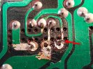
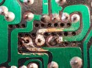
Well, I desoldered the TR712,5 transistors just to take a look at the traces, and sure enough one of the outside traces on one is broken. It looks like someone's been here before me because there are a lot of ugly scrape marks. I am guessing someone unroofed the copper so that they could make a solder connection with the intact part of the trace. Maybe that's common practice. Anyway, I did the same. Relay now clicks!


WhatsApp Image 2024-07-16 at 12.15.21 PM (1).jpgWhatsApp Image 2024-07-16 at 12.15.20 PM.jpg

Anyone know where this little wire off of E goes? Seems to maybe be headed to E1-E3 on the filter board?

WhatsApp Image 2024-07-16 at 12.15.21 PM.jpg
 
  • Like
Reactions: mbz
I soldered the E to the E3 on the cap board cause that seemed like the only place it could be going, and ground is ground. Please tell me if that's a bad idea.

@mbz I couldn't find the transistors you mentioned. Wish this CR had a nice image of the actual boards/traces like we have with the CA.
 
  • Like
Reactions: mbz
What is your bias? What is your DC? What are your rail and regulated voltages? Every one of these I have been in have had a need for full restoration of the regulated voltage board. Once you get all your voltages squared, then focus on protection and relay
Bias was set to 10mv between TP1-O.

I'm getting 50v on the main circuits.

I need to look into how to measure the other stuff.

'b' measures 94.6v - not sure what b is.


Edit: looks like avionics posted voltages here, so b, B+ and B- are certainly ballpark. Idle is good. Do I even need to adjust anything?
 
Last edited:
Well, I desoldered the TR712,5 transistors just to take a look at the traces, and sure enough one of the outside traces on one is broken. It looks like someone's been here before me because there are a lot of ugly scrape marks. I am guessing someone unroofed the copper so that they could make a solder connection with the intact part of the trace. Maybe that's common practice. Anyway, I did the same. Relay now clicks!


View attachment 3252882View attachment 3252883

Anyone know where this little wire off of E goes? Seems to maybe be headed to E1-E3 on the filter board?

View attachment 3252875
1721183133405.jpeg
 
If you want to support an outstanding AK member, consider buying from dgwojo. I’ve bought from him and he is very responsive and knowledgeable. His website is dgwojo.com or email at dwojo69@msn.com.
 
I'm going to replace the gross green lights with regular incandescent lamps. I can't look at that.

This seller is also an outstanding AK member. I've bought many different parts from him with never a problem.
 
I'm going to replace the gross green lights with regular incandescent lamps. I can't look at that.
For my CA-810 I went through a dozen different types of LEDs, sanding, dropping resistors to get it right. I think if I knew then what I know now, I’d stick with incandescent.
 
Well, if only things were that easy - I hooked up some speakers and I have an ongoing and decently loud hum.

Details of the hum:
-absent if coupler turned off
-absent if speaker output turned off
-present at low level even with volume turned all the way down
-does not increase with volume on inputs, aside from phono
-louder on phono, and increases with volume on phono
-if I increase volume to max on Aux, I faintly hear the FM (maybe unrelated)
-can be manipulated with the balance knob (as in, disappears on the side I turn it away from)
-seems louder if I flip the 15 hz low filter, and much louder still with 70 hz filter

My +/-25 are 26.3v and -22.4v.

Thankfully it's much easier to search these forums than it is to troubleshoot - I believe I have the same problem that was detailed in this thread: https://audiokarma.org/forums/index.php?threads/yamaha-cr-2020-hum.1038575/

The problem points to TR714 which happens to be adjacent to the already-problematic high heat TR712,715. I think I will replace these set of four transistors and might even attempt to displace TR712,715 from the circuit board, as others have done. I guess I should test the smaller ones out of circuit.
 
The problem points to TR714
Symptoms suggest issue with regulated power supply so maybe TR714 or...

Hums can be tricky, a good starting point is to measure the hum frequency, ie, 50/60Hz or rectified 100/120Hz.
The regulated psu only "sees" rectified 100/120Hz, so if you measured 50/60Hz then look elsewhere...

Mobile phone ap like spectroid or pc freeware like audacity can be used to determine hum frequency.

Thankfully it's much easier to search these forums than it is to troubleshoot
Certainly search AK, sadly many don't...
 
I believe the hum is higher freq, hence why it's louder with the 70 hz filter flipped vs the 15 hz, but I guess I should check.

I tried resoldering the TR713,4 today but it didn't make the hum go away. This board is really a mess and I'm idly wondering whether I should get a pcb riveter if there's a cheap one available. As for the current problem, I suspect one or more transistors might be bad.

BUT I'm going to put this on the backburner; will finish working on the CA1000 first. Things were getting a bit too confused in my mouser cart, too crowded on the workbench, and I'm also always doing woodworking projects.
 
Back
Top Bottom