• The move to the new server is done. There are some software and database maintenance updates in process. This has us passing the hat around to help out. We appreciate any donations. Seriously, even a dollar helps. The payment page may be found here - https://www.audiokarma.org/support.html

SOLVED: Intentionally-loose wires in SX-626 help check the bias

dlucy

dlucy67 (Doug)
Staff member
Moderator
Subscriber
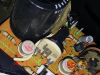
I've just started restoring my first SX-626 and I'm carefully recording all the caps, transistors, etc. to compare against the service manual... and there are two loose wires, just hanging out in space, apparently intentionally.

Why?

These look like they came this way from the factory, they are neat, and the PCB has holes for them... but I don't see any markings and find no reference to them. What do they do? Some kind of temperature compensation or sensing to adjust the bias during operation?

IMG_1498.png IMG_1499.png IMG_1502.png SX626-loose-wire-schematic.png
 
Register to hide this ad
sensing to adjust the bias during operation

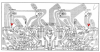
This must be correct. Wires are from the emitters of the lower outputs. Bias would be measuring the voltage from the lead to ground, then divide by the emitter resistance (0.5 according to the schematic)
 
Last edited:
Yes, this is how the bias is checked (positive lead of your meter to the wire, neg. lead to chassis). If you do nothing else make sure to replace the ceramic bias control pots (VR3 and VR4). Do not leave the old ones in there, they are notorious for going open or very high without provocation which will turn the transistors on hard and blow the outputs among other things. I have had a bunch of these old push-pull quasi-comps come through here (the SX-626 especially) with one of the rail fuses blown and every single time it's been because of a bad bias trimmer. Sometimes they work for a while but if you check the bias you will find it way too high (output Q temp will give it away too). If the previous owner didn't replace the fuse and try to get it to work then maybe the outputs won't be blown, but usually they try a whole 5 pack of fuses and fry the outputs and drivers before giving up.
 
Last edited:
Yes, this is how the bias is checked (positive lead of your meter to the wire, neg. lead to chassis).

Unbelievable! They are just HANGING there in space, waiting to reach out and short somewhere... I mean, I believe YOU, but man! What were they THINKING?

If you do nothing else make sure to replace the ceramic bias control pots (VR2). Do not leave the old ones in there, they are notorious for going open or very high without provocation which will turn the transistors on hard and blow the outputs among other things. I have had a bunch of these old push-pull quasi-comps come through here (the SX-626 especially) with one of the rail fuses blown and every single time it's been a bad bias trimmer. If the previous owner didn't replace the fuse and try to get it to work then maybe the outputs won't be blown, but usually they try a whole 5 pack of fuses and fry the outputs and drivers before giving up.

Great advice. Thank you!
 
They should be taped to the output capacitors, sometimes they have a bit too much conductor exposed and sometimes they are clipped neat. I've never seen one touch anything or cause a problem but yeah, seems like it could short if one doesn't know they are there and is moving things around inside. Most older QC amps had this setup, it seemed to be a fairly common practice BITD.
 
Yes, this is how the bias is checked (positive lead of your meter to the wire, neg. lead to chassis). If you do nothing else make sure to replace the ceramic bias control pots (VR2). Do not leave the old ones in there, they are notorious for going open or very high without provocation which will turn the transistors on hard and blow the outputs among other things. I have had a bunch of these old push-pull quasi-comps come through here (the SX-626 especially) with one of the rail fuses blown and every single time it's been because of a bad bias trimmer. Sometimes they work for a while but if you check the bias you will find it way too high (output Q temp will give it away too). If the previous owner didn't replace the fuse and try to get it to work then maybe the outputs won't be blown, but usually they try a whole 5 pack of fuses and fry the outputs and drivers before giving up.

What is the bias supposed to be set at on the 626? I didn't see it in the manual.
 
This pretty well covers it. The measurement across the emitter resistor is done between the flying lead mentioned above and the chassis ground, voltage measurements are taken from the metal cases of the TO-3 outputs and chassis ground. http://www.audiokarma.org/forums/in...t-bias-offset-on-sx-626-early-version.738142/
You've got to get the voltage properly adjusted too, but above all don't trust the original ceramic bias trimmers in the 626, they are a well known problem.
 
Here's an even more detailed explanation from Mark including the collector voltage balance adjustment:
vr1 and vr2 set an internal voltage in the amp for halfway between 0v and the 58 v (or so) power, vr3 and vr4 set the idle current in the output transistor stages, which flows from + 58v through Q10, R32 (0.5 ohms), q12 & R34 (0.5 ohms) to ground or zero volts.

Set VR3 and VR4 to zero ohms for zero or minimum idle current since work was done to either the power supply or the amplifier.

measure the voltage on the metal case of Q10 (to ground), then use VR2 to set the voltage on the metal case of Q12 (to ground) to half of Q10's measured voltage.

measure the voltage ACROSS (one dmm lead on each side of the resistor) R32 and use VR4 to set it to 15 millivolts.

transpose the numbers for the other channel.Q9, R31 (0.5 ohms), q11 & R33 and VR1, Vr3.
 
Last edited:
Also - my apologies, I misspoke: the bias trimmers are VR3 and VR4 on the schematic. VR1 and VR2 are the collector voltage adjustment trimmers, I corrected it in my original post but since it's been quoted I wanted to make sure people won't get them confused in the future.
 
You can use these wires if you want. I usually cut them off completely, and just solder a couple of pieces of scrap wire across the emitter resistors. These wires can be brought out for testing, and then removed once the levels have been set. If you're recapping the board, it makes sense to replace the small signal transistors as well, and all four trimmers as well.

Lee.
 
You could do it that way too, but you would only need to bring out one piece of wire per channel as the other end of the emitter resistors are tied to the chassis ground. The nice thing about having a test point lead left there is that you can check the bias very quickly and easily next time you are in the unit. It does sometimes drift a little even with all new components (though it's not super critical as long as it's pretty close).
 
Back
Top Bottom