• The move to the new server is done. There are some software and database maintenance updates in process. This has us passing the hat around to help out. We appreciate any donations. Seriously, even a dollar helps. The payment page may be found here - https://www.audiokarma.org/support.html

SOLVED: MC2105 Mono Re-Wire; Also, Terminal Block Notes

Johnny_Law

o.O
Subscriber
A previous owner (likely a recording studio) re-wired my MC2105's Input Coupling switch, I can't fathom why.

Any ideas?


The input blocking capacitors (C1, C2 0.22uF mylar) are removed.
In "normal", the input signal passes directly to the input board (the wires from the input jacks are soldered to the wires to the input board, directly on the switch, as seen)
In "direct", two things happen: (1) L&R inputs are shorted together, and (2) L&R 4ohm autoformer outputs are shorted together (note the red wires).
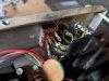
PXL_20210530_162239482.jpg

(Note they also soldered the ground & 8 ohm outputs directly to speaker wire ...)

PXL_20210530_162259091.jpg

For reference, here's how it's supposed to look (credit to this YouTube video):
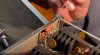
MC2105 Input Coupling Switch Original.jpg

And here's the original circuit:

MC2105 Input Coupling Switch Circuit.jpg
 
Register to hide this ad
To be specific - when I said "looks like exactly what it is" I meant it matches the 2100 circuit exactly, not that it's a bridged mono. :deal:

Suppose I'll leave it this way, it may come in handy.
 
I left the mono-switch as-is (what if I find another MC2105 someday :naughty:).

I re-wired the autoformer outputs to brand new terminal blocks, replacing the originals which were in bad shape. I thought I would share my lessons in this regard:

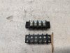
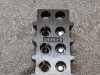
The original terminal blocks are 8-position (also called 2-row 4 position), with 0.375" spacing, open back. There are pins held in place with 6-32 screws. The pins extend back through the other row, extend through the frame, and are soldered to the autoformer wires. The original terminal blocks were made by Kulka.

PXL_20210613_170522076.jpg

PXL_20210613_170819812.jpg

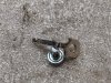
If you need individual replacement pins, you can find these on Mouser, part # 538-Y140.

PXL_20210613_170626503.jpg

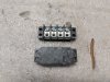
If you want to replace the original 2-row terminal blocks with new 2-row terminal blocks, the closest I could find are Mouser 504-TB100-04 which have a closed back. You would need to drill through the terminal block in one row, and install the aforementioned solder pins.

PXL_20210613_170504706.jpg

I decided to use a single-row equivalent, which fits perfectly and does not use those right-angle solder pins. It's a Molex part, Mouser 538-38710-6204. The pins are built into the terminal block. However, the pins are shorter, and you must be careful that the soldered autoformer leads don't short to the frame when installed.

I didn't take pics before installing, so here they are installed. Note that the original 6-32 machine mounting screws are too short, since the mounting flange is thicker than original. I used 3/4" long 6-32 screws from Ace, and took the opportunity to switch to Philips head from slotted to match the new terminal screws.

An additional note, I've found there are two types of the gold banana-adapters seen below. Some are thin (which fit within the original terminal block spacing), some are thick (which just barely don't fit). These terminal blocks have a hair more room, so they will accept the thicker adapters which is what you see installed.

PXL_20210613_170412177.jpg

PXL_20210613_170417407.jpg
 
Last edited:
Back
Top Bottom