• The move to the new server is done. There are some software and database maintenance updates in process. This has us passing the hat around to help out. We appreciate any donations. Seriously, even a dollar helps. The payment page may be found here - https://www.audiokarma.org/support.html

SOLVED Sony STR-6055: Distortion on Left Channel only when speaker connected & selected

Johnny_Law

o.O
Subscriber
Symptom: Left channel is distorted, but only when the speakers are selected and connected.

Test 1 settings: Headphones plugged in; 8 ohm speakers connected to Main speaker terminals.

Speaker knob to Remote / Off: No distortion through headphone left channel
Speaker knob to Main / Both: Distortion through headphone left channel & distortion through left speaker

Test 2 settings: Headphones plugged in; no speakers connected

Speaker knob to Remote / Off: No distortion through headphone left channel
Speaker knob to Main / Both: No distortion through headphone left channel

Other measurements / diagnostic work done:
DC offset under 10mV both channels; DBT dim (to confirm OPTs are OK)
Swapped L to R inputs from Tone Amp, distortion remains in left channel (isolating problem to amp)
Swapped L to R speakers, distortion remains in left channel (eliminating a bad speaker as a cause)
De-oxited Speaker knob (to eliminate dirty contact as a cause)

Repairs done thus far:
Re-flowed many solder joints
Confirmed all transistors on the tone board are operational
De-oxited all the pots & switches
Re-capped power supply, power amp, tone control, and equalizer boards (the channel was totally out before the re-cap and no, I didn't re-cap it thinking it'd solve the channel being out, I wanted to eliminate bad caps as a possible cause before repairing the channel)

Next steps:
I imagine I could start swapping components L to R on the amp board, and see if I get lucky.
Any ideas???? It seems like the additional load of the speaker may be causing something to clip? I don't have an oscilloscope so can't look at the signal but it sounds super distorted, like a radio station with bad reception.

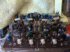
The patient:
IhXSKOC - Imgur.jpg

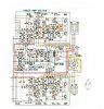
The circuit diagram, tracing the headphone & speaker signal wires (if helpful):
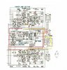
x283gSg - Imgur.jpg
 
Last edited:
Register to hide this ad
I don't see it on the schematic but does the signal to the speakers go through a relay? Might be a dirty relay.

Nashou
 
So looking more closely at the amp board, someone's been in there before. I noticed an NTE190 in place of Q707. Thinking maybe the 2SC1124 at Q707 went bad before, it may be the 2SC1124 at Q757 going bad now. So I went to swap Q707/Q757 and a leg of the NTE190 broke. Fortunately I have spare 2SC1290 on hand, so I used them (thanks @EchoWars) ... still distortion on the left channel. So that wasn't it.

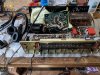
Here's a closeup of the board before I replaced those. You can spy a couple replacements from previous work ...

oEcK8jU - Imgur.jpg

I don't see it on the schematic but does the signal to the speakers go through a relay? Might be a dirty relay.

Nashou

Thanks! Hmm, I looked and don't believe there are any relays in there. Dang coulda been an easy fix!
 
Last edited:
What do you measure for voltage across R733/R734 (the 0.47 ohm resistors) with the speaker disconnected and connected? Compared to the good channel?
 
I would check those 2 emitter resistors (0.047) to see if one is open, as this can cause distortion. I would also check those 10 resistors (The ones connected to the collectors of each driver transistor to make sure they are OK, as well as check that 100 ohm resistors connected to the base of one of your outputs. If all of the resistors check OK on an ohm meter, I would check the outputs and drivers, to make sure none are open typically B to E. You can check them B-E using an old fashioned analog ohm meter, or you can get some of those small grabber type leads, clipping them to the B and E connections of each output, first, and then each driver next, using a voltmeter (I assume digital). If you read anything above 0.6- 0.7 volts, it usually indicates the transistor is open, or is opening under load.
Remember, the ohm meter is used to check things with power off, and unplugged. The voltmeter is used with the mini grabber type leads. Have the unit off, clip on the leads to the B and E connection of a transistor under test, and then power on. Shut down, remove the leads, and connect to another transistor to be tested. Then power on again.
Good luck
 
Do the .47 Ohm 2 watt resistors measure ok?

Nashou

What do you measure for voltage across R733/R734 (the 0.47 ohm resistors) with the speaker disconnected and connected? Compared to the good channel?

I would check those 2 emitter resistors (0.047) to see if one is open, as this can cause distortion. I would also check those 10 resistors (The ones connected to the collectors of each driver transistor to make sure they are OK, as well as check that 100 ohm resistors connected to the base of one of your outputs. If all of the resistors check OK on an ohm meter, I would check the outputs and drivers, to make sure none are open typically B to E. You can check them B-E using an old fashioned analog ohm meter, or you can get some of those small grabber type leads, clipping them to the B and E connections of each output, first, and then each driver next, using a voltmeter (I assume digital). If you read anything above 0.6- 0.7 volts, it usually indicates the transistor is open, or is opening under load.
Remember, the ohm meter is used to check things with power off, and unplugged. The voltmeter is used with the mini grabber type leads. Have the unit off, clip on the leads to the B and E connection of a transistor under test, and then power on. Shut down, remove the leads, and connect to another transistor to be tested. Then power on again.
Good luck

You guys rock - R734 is open. I measured all 4 in circuit first. The other three (R783, R784, R733) measure ~1 ohm in circuit. But R734 measured 150k in circuit! So I lifted a leg of R734, and it measured open.

Tomorrow I may swap one of the other three over just to confirm the signal cleans up, either way I'll order a new set of 4 with my next Mouser order.

In the meantime, I want to see if this makes sense as the cause ... I note from the circuit diagram, where R733 and R734 meet, is the white wire to speaker switch S8-1.

IpiJvUU - Imgur.jpg

Referring back to my trace earlier, adding an orange line to the junction of R733 and R734 ...

5EB81gE - Imgur.jpg

Yes, I think this makes sense from the circuit diagram perspective. Without R734 allowing the signal to pass through it, I am missing the input from Q710 (?) which is either the push or the pull? Would love a hand on this part! If someone can explain what distortion an open R734 would cause ...
 
Last edited:
You are getting the distortion because you are only getting 1/2 the audio signal out to the speaker. You are missing either the negative going signal, or the positive going signal.
But make sure to check tose output transistors, especially the one that R734 is connected to. Those 2w emitter resistors usualy burn open AFTER the output transistor shorted E to C.
 
You are getting the distortion because you are only getting 1/2 the audio signal out to the speaker. You are missing either the negative going signal, or the positive going signal.
But make sure to check tose output transistors, especially the one that R734 is connected to. Those 2w emitter resistors usualy burn open AFTER the output transistor shorted E to C.

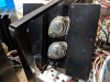
Thanks - makes sense! Looks like two of the Sony 2SD88s were replaced with PL909s. So one pair of 2SD88s may have failed previously.

COM94TT - Imgur.jpg

Edit: Pulled them out of the circuit, only one is bad, a PL909 (fails diode test between E/C both ways). The other is good as are the Sony 2SD88s. Also observed loose collector screw nuts and missing E/B heat sink through hole insulators from the previous work. :eek: Anyway so looks like I need to replace the PL909 pair.
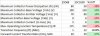
I do happen to have a set of 4 good 2SC1030s on hand. I think they might work. (Both the 2SC1030 and the 2SD88 have had the same replacement recommended, the MJ21194G, so they must be close ...)
 
Last edited:
Now to compare the two ... 2SD88; 2SC1030. I'd love if someone with more experience could offer any thoughts here.

04y7fC1 - Imgur.jpg

Worse:
  • lower max C power dissipation
  • lower E-B voltage
  • lower max operating temp
Better:
  • higher C-B voltage
  • higher C-E voltage
  • higher C current
  • higher HFE
Not sure:
  • much higher transition frequency
 
Last edited:
Those 2SC1030's will be fine. Just make sure to use a dim bulb tester after you replace the bad parts, on first power up test in case you still have issues like maybe bad drivers or others.
 
  • Put in the 2SC1030
  • Replaced R783, R784, R733, R734.
DBT is dim, and the sound is even and clean. :beerchug:

Idle current and DC offset adjusted per manual. Sounds fantastic. This has more power than I expected (IHF dynamic 100 watts into 8ohms; 140 watts into 4ohms)! It does not sound like a 'little' receiver.
 
Last edited:
Back
Top Bottom