• The move to the new server is done. There are some software and database maintenance updates in process. This has us passing the hat around to help out. We appreciate any donations. Seriously, even a dollar helps. The payment page may be found here - https://www.audiokarma.org/support.html

Some wiring confusion that needs rectifying

Carbsandcaps

Super Member
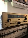
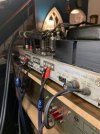
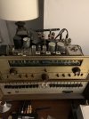
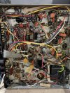
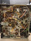
I bought a rare soundscraftsmen tube receiver. Recapped it and it’s working great. The part that confuses me is the rectifying circuit. One leg of the transformer goes to 2 opposite diodes producing a dc output. The other goes through a 150mf capacitor to ground. The transformer puts out 120v ac and somehow at the end of it I have 320v dc at b+. Can someone explain this? Is this technically half wave rectification? Third wave rectification?

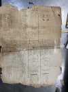
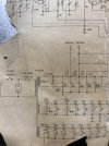
Included is the original diagram that was luckily included in the sale of the receiver that is reassembled like the Dead Sea scrolls. IMG_8397.jpegIMG_8398.jpeg
 
Register to hide this ad
This is whats called a voltage doubler. Very common in the early days of solid state rectification in tube gear.
Gadget, that 150mfd should be rated for say 200VDC, but the 100mfd in the voltage doubler circuit, should be rated for 400VDC. Right?

Thanks1
 
The 150 and the 100 can both be 200v caps. Each one will see about half the main supply voltage. The 40uf cap has to be rated to handle the full thing though, 400 volts or so would be typical.


whats a little odd is the unequal values in the doubler caps though. Its not absolutely critical that they match, but the output is less uneven if it does.
 
The 150 and the 100 can both be 200v caps. Each one will see about half the main supply voltage. The 40uf cap has to be rated to handle the full thing though, 400 volts or so would be typical.


whats a little odd is the unequal values in the doubler caps though. Its not absolutely critical that they match, but the output is less uneven if it does.
I was wondering about that. I guess you could just buy all 400VDC rated caps, and not worry about it. ;)
 
Congratulations for a great job on restoring the schematic! And successfully recapping the Soundcraftsmen receiver. Looks like you have a “Full Wave Series Multiplier” power supply - notice the two rectifiers. Often used on some Eico, HK and other pieces in the 60s.

Here is a nice explanation of multiplier rectification: https://www.electronics-tutorials.ws/blog/voltage-multiplier-circuit.html
thank you for the clarification makes you wonder why not just go with a “normal” transformer and center tap instead of going through all this. The transformer seems to run hot I don’t know if that’s a side affect of the multiplier rectification
 
Couple reasons, big one being its cheaper. Less copper in the transformer since there are less turns, so less expensive to make. Also rectifiers of the era didn't have inverse voltage ratings that were as high as commonly available now. The doubler allowed lower PIV diodes to be used vs what would be required for a traditional full wave setup.

likely runs hot because of high input voltage. Easy way to check is to measure the heater circuit. Should be 6.3 volts, but up to about 6.7 would be considered within tolerance. Beyond that it really should have lower input voltage.
 
Can't post a schematic of my Bogen M-120 using the tablet I am on at the moment but it also uses a voltage doubler circuit which looks exactly like yours except mine has 300 volts coming off of the transformer instead of 120, and it is doubled to 600 volts. It uses four 8417 output tubes with 605 volts on the plates. After several hours, my power transformer is barely warm to the touch so I wonder if it is just by design. Mine has also been recapped especially the power supply. I do remember that the power transformer used to get pretty warm, almost hot to the touch years ago before I did the recap.
 
No none whatsoever. It currently has no am radio but I think it’s because the capacitor fins are bent and touching.
Zero hum is very good news!

Does anyone listen to AM anymore? Actually, I listen sometimes on my shortwave receiver. You can get some interesting stations at the far extremes of the frequency range. Long distance stations when the atmospheric conditions are just right. :thumbsup:
 
Can't post a schematic of my Bogen M-120 using the tablet I am on at the moment but it also uses a voltage doubler circuit which looks exactly like yours except mine has 300 volts coming off of the transformer instead of 120, and it is doubled to 600 volts. It uses four 8417 output tubes with 605 volts on the plates. After several hours, my power transformer is barely warm to the touch so I wonder if it is just by design. Mine has also been recapped especially the power supply. I do remember that the power transformer used to get pretty warm, almost hot to the touch years ago before I did the recap.
My MO 100A is similar, but closer to 700v. Only runs 2 kt88 or similar these days. Cool as a cucumber, but its an under stressed industrial amp designed to be turned on and forgotten about in a closet for years. Consumer grade stuff tends to not be quite so over built
 
The 150 and the 100 can both be 200v caps. Each one will see about half the main supply voltage. The 40uf cap has to be rated to handle the full thing though, 400 volts or so would be typical.


whats a little odd is the unequal values in the doubler caps though. Its not absolutely critical that they match, but the output is less uneven if it does.
You think I should match the doubler caps? And if so would you do the 150uf or the 100uf? I don’t mind experimenting even if the benefits are minimal
 
Back
Top Bottom