• The move to the new server is done. There are some software and database maintenance updates in process. This has us passing the hat around to help out. We appreciate any donations. Seriously, even a dollar helps. The payment page may be found here - https://www.audiokarma.org/support.html

Sony 6060f Receiver no output

markk

Active Member
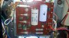
The unit powers up and the lights go on. All switches seem to function. Sprayed all knobs and switches with deoxit. I've tried the tuner and Aux connected to other sources. Still no output. The unit doesn't get warm which suggest to me something wrong with the power transistor rails...? I've removed the top cover unit but nothing suspect. There are a number silver boxes that I think are for the tuner. Opening up the bottom panel I found a bulged capacitor near a soldered in white fuse (with hairline crack?). Any idea what type of fuse this is? Also, the base of the two big power caps look a bit singed..from soldering? I'm thinking I should do a whole unit recap. Any additional guidance would be greatly appreciated. Have multimeter. TIA!
 

Attachments

  • sony 6060 012.jpg
    sony 6060 012.jpg
    73.1 KB · Views: 116
  • sony 6060 019.jpg
    sony 6060 019.jpg
    74.1 KB · Views: 110
  • sony 6060 022.jpg
    sony 6060 022.jpg
    70.7 KB · Views: 100
  • sony 6060 023.jpg
    sony 6060 023.jpg
    58.7 KB · Views: 91
Last edited:
Register to hide this ad
This model is one of the best sounding receiver ever built. But it is like 40+ years. I hope you get it going.
 
First I would replace the 2 caps,then if it works I'd consider replacing all of them,and maybe the fuses as well.
 
If your multimeter has a diode test function (or resistance measurement function) test the white fuse WITH THE POWER OFF; it should have no resistance or 000 value at your meter when in diode test function.

Then, switch on the amp, put the multimeter in DC volt, and measure the tension across the fuse. If it has blown, then some voltage (up to 80V) can be around it. Then measure the DC voltage on the solder points of the black and brown wire above the fuse; this should be around 80Vdc if the fuse, transformer and power supply caps are still working.

The two capacitors on the power supply board are buffer/filter capacitors for the power going to the tuner section, they are not related to the power supply going to the amplifier stage. Measure the tension across the legs of the 1000uF/35V one (the bulgy one), it should be around 24 Vdc. I agree that this one is looking odd, perhaps faulty, but you need to cut the plastic sleeve to get more details. The tension across the 500uF/25V one should be around 15 Vdc.

Please tell what the outcome is.

The two large can capacitors next to the transformer, are NOT the power supply cap. These are the output coupling caps between amp output and speakers. This amplifier has a single power rail, and the output of the amplifier is therefore at half of the power rail (40Vdc), these caps are there to block the DC to speakers, and let the AC music signal through. If they are bad they will distort the music signal, but not provide a dead amp. Replacement by high quality caps will be make huge difference.

The power supply of the amp section has only one power supply cap (not on a PCB), which is 2000uF/90V, horizontal position under the transformer.

That's the one to look at for failure.
 
Many thanks for you response. I unsoldered one lead and tested the continuity of the white fuse (5 amp). Continuity failed. Bad fuse right? Will look at your other advice in more detail. Thanks again, Mark
 
tension across the fuse ~70 volts
black and brown wire tension 0 volts
black and red wire tension 0 volts
black and red wire right ~37 volts
1000uF/35V cap (bulgy one) 30volts
500uF/25V cap 15 volts
 
I had my tech go through my example and get it up to speed. I recommend professional help by someone competent.

Why? My tech noted that Sony over-engineered the design and made it very complicated, reaching for competitive advantage in teh new US market. For example, there are individual power storage capacitors off the rail for each gain stage. The muting circuits on the FM are also rather complicated.

Get it done right - you'll be glad you did.
 
tension across the fuse ~70 volts
black and brown wire tension 0 volts
black and red wire tension 0 volts
black and red wire right ~37 volts
1000uF/35V cap (bulgy one) 30volts
500uF/25V cap 15 volts

You should see 80V input to the fuse. I had a bad power switch on mine which caused it to read about 70V. Not good.

Br/Bl go to main filter cap, if fuse blown, 0V is normal.

1000/35V cap 30 volts, same as my working unit, still replace bulging cap.

500uf/25V cap 15V normal as compared to mine.

Do not follow my advice without another post confirming what I suggest.

If you remove brown/black wires from the main filter cap and read them out for a solid short you might be able to see the cause of your blown 5A fuse.
If there is no solid short seen out from the main cap you might be able to try a new fuse. If you see a solid short you will have to look at the power transistors, power amp boards and/or protection board.

I wouldn't recap until you find the cause of the blown fuse.

If you can't/don't want to fix it I could always use a parts unit:D
 
Thanks rswojo. Last night, I did replace the 5A fuse and it blew as soon as power switched on. (Bad switch - where do I find a new power switch?) Since the new fuse blew right away, I should look into the power transistors, power amp board and/or protection circuit (?). I think I'm going to need a parts diagram/schematic before proceeding. Do you happen to have? What do I need to measure on said "power parts"?
 
There should be a "sticky" somewhere about measuring/checking output transistors. If they are toasted other components might have been cooked also. I would start by measuring/checking the output transistors.

The power switch is the least of your problems now. The short needs to be repaired before you begin to worry about the power switch. The power switch is almost unobtanium, if you get that far.

I AM NOT an expert. I have fixed a few simple things but I am not qualified to provide tech support. Hopefully one of the resident expert techs can help with this.

PM me with your email address and I can send you a copy of the service manual (about 20M).


Here are .jpg's of the amp schematic.

View attachment 372105

View attachment 372106
 
Last edited:
Indeed, find the transistor check sticky post and start from there.

To return to the 70 Vdc measured in lieu of the referenced 80 Vdc, that faulty power switch is a good feedback from rswojo, and I definitely worth looking into. Little note though: in order to 'loose' some 10 volts, there must be a current flowing, which is hardly impossible with the fuse open. So the 10 volt loss must IMO come from somewhere else; the options being:
- one or more of the diodes or capacitors upstream the fuse are bad
- the voltage selector vs your mains voltage is different
- and a combination of mains voltage difference with manufacturing tolerances
The 80 Vdc in the schematic is not a holy property, but 70 volts is getting too much offset, for sure. And why this happens under no load (no current) conditions is yet to be determined. Perhaps checking the voltage drop across each diode might shed some light.

And checking out the output transistors of course.

When the output transistors are all out, turn on the amp with new fuse, and dimb bulb tester.
 
I read all four as NPN transistors (the top two were marked Sony 2SD88 E35). These are the four attached to the big heat sinks. BTW, my meter was set on the diode fxn which was also 2K ohm. Details are as follows:
top right
black lead to base, red lead to collector, result = 0.00
black lead to base, red lead to emitter, result = 0.079
red lead to base, black lead to collector, result = 0.00
red lead to base, black lead to emitter, result = 0.086
black lead to emitter, red lead to collector, result = 0.086
red lead to emitter, black lead to collector, result = 0.079

bottom right
black lead to base, red lead to collector, result = 0.073
black lead to base, red lead to emitter, result = 0.00
red lead to base, black lead to collector, result = 0.081
red lead to base, black lead to emitter, result = 0.00
black lead to emitter, red lead to collector, result = 0.073
red lead to emitter, black lead to collector, result = 0.081

top left
black lead to base, red lead to collector, result = 0.518
black lead to base, red lead to emitter, result = 0.466
red lead to base, black lead to collector, result = 0.518
red lead to base, black lead to emitter, result = 0.600
black lead to emitter, red lead to collector, result = 0.111
red lead to emitter, black lead to collector, result = 0.111

bottom left
black lead to base, red lead to collector, result = 0.515
black lead to base, red lead to emitter, result = 0.456
red lead to base, black lead to collector, result = 0.642
red lead to base, black lead to emitter, result = 0.520
black lead to emitter, red lead to collector, result = 0.112
red lead to emitter, black lead to collector, result =0.112
 
The ones on the right side are dead; base to emitter shall read 0,50~0.70 V, and the collector to emitter is a short circuit.

Looks like a case of replacing all four of them together, to maintain equality (in sound/dynamics) between the two channels

Now that the trannies are out, can you *safely* switch on the amp with new fuse in place? (Safely: none of the wires of the removed transistors are touching something, not an issue if they are socketed)
 
Last edited:
I had my tech go through my example and get it up to speed. I recommend professional help by someone competent.

Why? My tech noted that Sony over-engineered the design and made it very complicated, reaching for competitive advantage in teh new US market. For example, there are individual power storage capacitors off the rail for each gain stage. The muting circuits on the FM are also rather complicated.

Get it done right - you'll be glad you did.

I read about this many years ago.....that power storage was distributed.

This model really needs a competent tech.

Sony was trying to impress: The knobs and speaker terminals are solid aluminium. :D
 
Where to buy replacements for Sony 2SD88 E35?

The 2SD88 will be very difficult to find. Typically the On-Semi MJ21194 or MJ21194G is used as a replacement for this kind of amps. Now where to buy them is the question, because many of the MJ21194 offered on auction are counterfeits, so you ought to buy them from a reliable source such as Digi-Key, Mouser, etc. The issue being with those large retailers is that you pay a lot of shipping costs if you stay under a certain order value. So it's best to list as many components you need (and consumables such as the thermal paste between heatsinks, mica washers and transistors)

I hope you recovered the mica washers; nicely clean them with white spirit, then soap and water, so that you can re-use them. If damaged, then to buy some new ones.
 
Many thanks Oilmaster. BTW. I switched on amp with new fuse sans trannies - no blow! Checked the voltage again at the fuse and I see 79V. From previous posts, this is good. Not sure what I saw before.

Regarding the transistors:

1) There was also some insulation around the emitters and collectors. Is this something I should replace on the new installs?
2) There is a small ceramic cap(?) on top of the bottom trannies - not connected to the trannies. Anything additional concern with these?
3) Looks like I need to put together an order. What are the priority caps for replacement? I got a list from another poster.
 
Last edited:
Good to hear the fuse didn't blow sans trannies. Althought there are many aged capacitors in there, it means that there are no shorting ones (but it doesn't mean that they are all healthy either). At least they hold tension, which you can use to do some further verification if the remaining circuit is ok.

In the circuit diagram you can see on many places the little blue arrows with a blue value written. These are the DC values which should be there (with the volume knob at zero !, input select to tape or aux). Perhaps you have a B&W copy, but you should still see the arrows with values. Now, please check each one of them on the amp boards, BOTH channels. Easiest might be to mark off each one of them on the schematic when you go through. Of course, the 38.5 volt at the emittor of the removed trannies will not be there, it's floating at the moment, and the output rail as such (normally 38.5V) migth be floating as well, but the rest should measure more or less as indicated.

Also check the DC values in the protection circuit.

EDIT: the DC values are measured from a zero volt reference point; find a suitable point to hook-on the black probe of your multi-meter to zero (such as the minus terminal of the power supply cap), or another point on the amp PCB. Also, be careful when measuring: slipping the probe(s) by accident to the leads on another component when you are in there might easily blow one or more small trannies!

Depending on the outcome, you might need to order some other trannies.

regarding you questions:
1) can you post a picture? ot other AK member knows this?
2) this is a thermistor, Th801, which is the temperature monitor which would activate the protection circuit if the output trannies become to warm. For the moment, nothing to do, only to be re-installed correctly.
3) what to order... this is a tricky question. If it were only the output trannies, then you would rightfully invest more... and if you order only the trannies it's a waste of shipping costs... My point being that I would not like to drive you to spending money on an amp which might have multiple complex issues which you don't know yet. But if you take your own decision on it, then the usual thing is to replace the electrolytic capacitors. However, the 3 big ones (power supply and output coupling) are not found with Mouser/Digikey; but from a handfull specialised shops. (if you would take the solder lug models from Nichicon KG-series).
 
Last edited:
Back
Top Bottom