• The move to the new server is done. There are some software and database maintenance updates in process. This has us passing the hat around to help out. We appreciate any donations. Seriously, even a dollar helps. The payment page may be found here - https://www.audiokarma.org/support.html

sony hp-210a repair help.

TrevorBarten

Well-Known Member
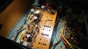
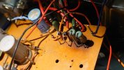
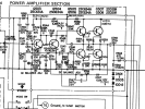
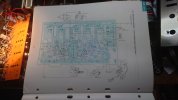
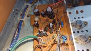
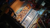
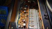
I have a sony hp-210a all in one system that has some issues with the power amplifier section. 3 of the 4 power transistors are shorted to ground and the resistors directly in line with the top two got completely toasted. I ordered some replacement d291 transistors from alie and I am checking around to figure out what else needs to be replaced. I have two questions, 1 is how I can figure out what resistors I need. The ones that used to be on there are unrecognisable. I thought that it may have been the same for both channel but the one resistor that is still visible is different from the one on the other side in the same position. Also the number of resistors is different. I checked the service manual but since the board has no part labels I couldn't figure out what I had to look at. My second question is what exactly the tiny black/purple things are. I assumed them to be diodes but the ones in the middle do not beep at all in diode mode while the two in the back next to the two green resistors beep both sides, the resistance reading one way is 0.3 ohms and the other way is around 40k which does make me think they might be diodes. The text on them says ir2l or k2l iirc. Please view the pictures included below for a visual aid.
4eabfc5a-fa70-463e-bed1-b491a2c77b53.jpeg01b398d1-5d04-4243-aabd-695df663b0f5.jpeg828b7f07-c6d0-4c8e-961a-497130599fad.jpegservice.PNG
 
Register to hide this ad
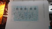
i looked at 3 sources for the service manual and every one is missing the board view for the amplifier and that is what you need.

the only suggestion that i have is to contact the seller on ebay that has the original manual and as them to verify that pages 36,37,38 are there and have the amplifier board views that you need.

if so, buy the manual from them.

this would be better than nothing but it still leaves the potential problem of a design change and different components used after the manual was printed.

i am not too sure that i would invest the almost $40 for the manual plus parts on this unit. but if i was tasked to repair this unit, that would be what i'd do.

good luck.
 
i looked at 3 sources for the service manual and every one is missing the board view for the amplifier and that is what you need.

the only suggestion that i have is to contact the seller on ebay that has the original manual and as them to verify that pages 36,37,38 are there and have the amplifier board views that you need.

if so, buy the manual from them.

this would be better than nothing but it still leaves the potential problem of a design change and different components used after the manual was printed.

i am not too sure that i would invest the almost $40 for the manual plus parts on this unit. but if i was tasked to repair this unit, that would be what i'd do.

good luck.
Thank you for the tip. I personally also would not pay even the 40 usd I already spent on the output transistors on this but it has sentimental value to the person that asked me to look at it. I will contact the ebay seller.
 
It has been a while and I would like to ask for some advice again.

I have since purchased the service manual with the correct pages. I have replaced all the electrolytic capacitors on the power amplifier board, replaced the diodes, replaced the resistors and the output transistors but I am still having issues. The device turns on but one specific resistor gets very hot. I checked the surrounding transistors and they test ok with a multi meter. If I remove the two transistors for that channel I can get the device to turn on and stay on without anything becoming very hot.

However the electrolytic capacitor that is next to the power input that I initially replaced blew up and I have now put back the original one. However I believe that one will also blow soon since while the device was plugged in but not turned on the lights suddenly started to slowly turn on and become brighter.

Ignoring the cap I am not able to get the amplifier to produce sound. Granted I turned the bias pots all the way down but even playing around with them does nothing. If I turn the volume knob I do hear crackling. And when turning I can hear the signal faintly in the right channel (with the transistors for the left channel removed) but this is paired with a dimming of the lights of the amplifier.

Of note is that I replaced some of the capacitors with ones that have a higher maximum voltage rating which I do not think is an issue, I also noticed that in the service manual the cap that blew up is different from what was on the board, 220 uF instead of the present 470uF. However the service manual is for the 210 which has a fifth output transistor which is missing on the 210a it seems. Aside from this the output transistors have a voltage drop across the pins of 0.17 in circuit both ways around. Also when turned on there is a constant buzz/hum. If I increase the bias this hum increases as well.

So with all that information I am wondering what the issue could be. I assume the 16v capacitor is causing some power issues. But aside from that I am pretty lost. I checked most if the resistors out of circuit including the one that gets hot and they measured ok enough. I did not check all the transistors, only a few, could one of those be the issue? I will probably order all the parts on the board to attempt a full rebuild and go from there. Only thing is that I believe the 210a board has two resistors next to the fifth (missing) output transistors which aren't there on the service manual...

Pictures:
DSC_1405.JPGDSC_1406.JPGDSC_1446.JPGDSC_1447.JPGDSC_1448.JPG
 
Ok update, I found out that on the channel that is having issues there was a shorted transistor. I also figured out that the hum/buzz was due to me having taken the headphone jack out of the socket which means it is not grounded. If I touch it to the chassis there is sound from the signal. It is a little distorted but I presume that is caused by either the missing power control cap (I removed it for testing), the now missing transistor, switches and pots which have yet to be cleaned or the incorrect bias and dc offset adjustments. Pretty annoying that I just ordered parts from mouser if I only really needed the transistor but I might as well replace them all I suppose. I think it will be working after I do these repairs. I just hope that the reason the power cap blew out was either the incorrect uF rating which I doubt is the case or the shorted transistor which I think might make more sense. The power issue with the lights is also gone after removing the cap.
 
Back
Top Bottom