• The move to the new server is done. There are some software and database maintenance updates in process. This has us passing the hat around to help out. We appreciate any donations. Seriously, even a dollar helps. The payment page may be found here - https://www.audiokarma.org/support.html

Sony PS-X50 wow/flutter

Carterkent04

New Member
I recently received a ps-x50 and ever since i got it it has had terrible wow/flutter. I checked power supply voltage per the service manual, set the magnetic sensor correctly, and speed pots but nothing is doing any good. The motor is also a little loud. Has a consistent "rumble." Is the motor bad? Or do i need to adjust the hall and offset pots? Thanks in advance for any advice!
 
Register to hide this ad
I recently received a ps-x50 and ever since i got it it has had terrible wow/flutter. I checked power supply voltage per the service manual, set the magnetic sensor correctly, and speed pots but nothing is doing any good. The motor is also a little loud. Has a consistent "rumble." Is the motor bad? Or do i need to adjust the hall and offset pots? Thanks in advance for any advice!
Hi Carter, Did you ever find out what was going on with your PS-X50? I have a PS-X65 with over 3% W&F and cannot figure out what is causing it.

Thanks, Dave
 
Hi Carter, Did you ever find out what was going on with your PS-X50? I have a PS-X65 with over 3% W&F and cannot figure out what is causing it.

Thanks, Dave
So i found that if the magnetic sensor is not physically close enough to the platter it will create this issue. Also it is a very big trial and error on setting the pots with an oscilloscope. Keep in mind that a metal screwdriver will mess with readings when close to a potentiometer. First thing i would check is the magnetic sensor on the platter - if the x65 is the same as the x60.
 
So i found that if the magnetic sensor is not physically close enough to the platter it will create this issue. Also it is a very big trial and error on setting the pots with an oscilloscope. Keep in mind that a metal screwdriver will mess with readings when close to a potentiometer. First thing i would check is the magnetic sensor on the platter - if the x65 is the same as the x60.
I did check the sensor voltage output per the service manual and it was off and very difficult to get within the parameters of 20mV to 50mV. I'll need to check it again because I do not have an O-scope (need one badly!), and I was just making adjustments to the pots based on functional behavior. This unit was a mess when I got it, none of the controls worked properly and the tonearm was flying all over. Now all the functions work but still has this one issue. I do hear a tiny, constant tick from the motor though when its running. Not sure if the lubrication inside of the motor has dried up somewhat.
 
I did check the sensor voltage output per the service manual and it was off and very difficult to get within the parameters of 20mV to 50mV. I'll need to check it again because I do not have an O-scope (need one badly!), and I was just making adjustments to the pots based on functional behavior. This unit was a mess when I got it, none of the controls worked properly and the tonearm was flying all over. Now all the functions work but still has this one issue. I do hear a tiny, constant tick from the motor though when its running. Not sure if the lubrication inside of the motor has dried up somewhat.
What I found with the now 4 ps-x50, and x60 tables i have restored, the potentiometers are super sensitive, and even a cheapo oscilloscope does the trick. and even with the magnetic sensor being "within voltage" can still be too far from the platter side to pick up the magnetic tape on it. I basically just get the sensor as close as possible to the platter without scraping. That has seemed to do the trick on the W&F issues for me. On 3/4 platters.
 
I did check the sensor voltage output per the service manual and it was off and very difficult to get within the parameters of 20mV to 50mV. I'll need to check it again because I do not have an O-scope (need one badly!), and I was just making adjustments to the pots based on functional behavior. This unit was a mess when I got it, none of the controls worked properly and the tonearm was flying all over. Now all the functions work but still has this one issue. I do hear a tiny, constant tick from the motor though when its running. Not sure if the lubrication inside of the motor has dried up somewhat.
Just be careful on touching your leads to the posts for the motor, if you short out the Hall sensors you're gonna fry them in a millisecond and toast your motor. - ask me how i know
 
What I found with the now 4 ps-x50, and x60 tables i have restored, the potentiometers are super sensitive, and even a cheapo oscilloscope does the trick. and even with the magnetic sensor being "within voltage" can still be too far from the platter side to pick up the magnetic tape on it. I basically just get the sensor as close as possible to the platter without scraping. That has seemed to do the trick on the W&F issues for me. On 3/4 platters.
I did adjust the sensor somewhat from its original position. I probably should have never touched it though. I'll try to get it back to as close as possible to the rim of the platter without touching, and see if it makes a difference. Right now I think its about 2 mm out.
 
What I found with the now 4 ps-x50, and x60 tables i have restored, the potentiometers are super sensitive, and even a cheapo oscilloscope does the trick. and even with the magnetic sensor being "within voltage" can still be too far from the platter side to pick up the magnetic tape on it. I basically just get the sensor as close as possible to the platter without scraping. That has seemed to do the trick on the W&F issues for me. On 3/4 platters.
I tried to get the speed sensor as close to the platter as possible. It did drop the W&F down from about 3.5% down to 2.8%, but I can't get any lower than that. Are there any pot adjustments that can be made to lower it?
 
I tried to get the speed sensor as close to the platter as possible. It did drop the W&F down from about 3.5% down to 2.8%, but I can't get any lower than that. Are there any pot adjustments that can be made to lower it?
You can't resolve this without a scope. Check the speed adjust waveforms at 45 and 33 (do the 45 first as stated). They should be as shown in the service manual. If they are bobbling a lot and jumping around, either the mag reader is skipping or (which happened to me on a PS-X600) the CX193 (IC1 on yours) is bad. Do not probe around on the TT when powered. If you slip and short pins there's an excellent chance you'll kill the IC. I troubleshot my X600 for months refusing that stalling the platter would kill the CX193 because it looks protected (and is almost impossible to find). After changing a lot of parts (I even retuned the op amp feedback circuit), it was the CX193 after all. One way to know (looking back), is that if the motor output waveform has a lot of noise riding on the wave (like 1V), it's the op amp or the 193 that are bad. Do not run long with a very fuzzy motor output or by turning the gain up too far to get more speed (my TT was running slow just below the correct speed). I killed the transformer running it like this.

What did you measure wow and flutter with? I used RPM WOW app on the iPhone. My W&F went from .3% to .5% RMS to .07% RMS after replacing the CX193. But my circuit had no extra force to be able compensate for any drag. CX193 was bad preventing it from outputting the servo adjust to make up for the slow down.
 
You can't resolve this without a scope. Check the speed adjust waveforms at 45 and 33 (do the 45 first as stated). They should be as shown in the service manual. If they are bobbling a lot and jumping around, either the mag reader is skipping or (which happened to me on a PS-X600) the CX193 (IC1 on yours) is bad. Do not probe around on the TT when powered. If you slip and short pins there's an excellent chance you'll kill the IC. I troubleshot my X600 for months refusing that stalling the platter would kill the CX193 because it looks protected (and is almost impossible to find). After changing a lot of parts (I even retuned the op amp feedback circuit), it was the CX193 after all. One way to know (looking back), is that if the motor output waveform has a lot of noise riding on the wave (like 1V), it's the op amp or the 193 that are bad. Do not run long with a very fuzzy motor output or by turning the gain up too far to get more speed (my TT was running slow just below the correct speed). I killed the transformer running it like this.

What did you measure wow and flutter with? I used RPM WOW app on the iPhone. My W&F went from .3% to .5% RMS to .07% RMS after replacing the CX193. But my circuit had no extra force to be able compensate for any drag. CX193 was bad preventing it from outputting the servo adjust to make up for the slow down.
I just ordered an O-scope. I have been needing one for a while now. Hopefully I'll be able to get it dialed in perfectly with it. But I was using the RPM and RPM Wow apps to get the readings. I was able to fine tune the RV105 and 106 pots to get the speeds close to 33 and 45 within +/- .6, and then tweaking RV107 through 110 to get the W&F down to around .80%. I know that is still a lot higher than the spec, but its close enough for now. Not exactly sure what 107 through 110 do exactly though with the motor speed, if 105 and 106 control 45 and 33. The speed holds good though, so I was surprised that the W&F was so high. The sensor is positioned correctly also and I get around 25mV on the speed detecting head. Appreciate the help!!
 
Do you mean RV205 and RV206? They set the motor gain and although that does change the speed, RV201 and RV202 are the speed fine adjusts as they feed the servo CX193 IC. If you're watching the strobe for speed look for that to not move, ever. If a dot is moving left or right that's not good. I doubt you can see W&F on the strobe. If you lightly touch the edge of the platter and the dots don't move at all, that's a positive sign that the CX193 is functioning. I set the motor offset by powering up and making sure both motor outputs are 0V. If not centered without running, they won't be when running. When running I couldn't discern on the scope if the sine wave was centered. After all it is being adjusted by the servo. The peak to peak I did visually but my scope called it 4.2-4.4 peak to peak so I backed them off til the scope said 4-4.1 peak to peak which was the tiniest of an adjustment. My potentiometers were very closely set to the same position which was no surprise. I did change those pots out by the way. And replacements are slightly larger than the originals and it was a tight fit. I used sealed pots. I am also replacing the speed adjust pots because I found them very touchy but with all my fiddling I probably over exercised them.

Good luck. I'm watching if I can help. It meant a lot to me to get a turntable that I purchased when I was 20 working. And it's a nice one for my needs.
 
Its RV105 and 106 on the x65-
1744752479051.png

No strobe on this table either, but I have a Dual disk that I use, and the speed stays constant. These pots seem to be very sensitive also, but I should be able to fine tune when I get the O-scope.
 
Sorry I looked at the subject and saw X50 forgetting you did change to X65. I'm on the same page now (literally). This is very much like the X600 with an older processor. Do the motor peak to peak first because it can change the speed slightly if you make changes. Are your RV105/106 in good shape? My were clearly oxidized.

Yes, no strobe on the X600 too - I bought a strobe disk with the strobe LED module, but I didn't need the LED module because my LED can lights in my room are at 60Hz, so I just used the 60Hz line on the disc lol. That strobe output of the CX193 goes to the processor and I don't know if they measure that to light the LOCKED led. I do think that it's sampled because LOCKED seems to lag slightly when the speed goes off.

Good luck. Crossing my fingers that your CX193 is fine.

EDIT: Change C201 to a safety rated 250-400V cap and use 0.01uF. As that cap leaks it passes voltage possibly enough to power the TT at a low voltage even when it's turned off. Check the output of either secondary when it is powered off but plugged in and check the voltage. Check if you have DC voltage at any of the ICs.
 
Last edited:
Sorry I looked at the subject and saw X50 forgetting you did change to X65. I'm on the same page now (literally). This is very much like the X600 with an older processor. Do the motor peak to peak first because it can change the speed slightly if you make changes. Are your RV105/106 in good shape? My were clearly oxidized.

Yes, no strobe on the X600 too - I bought a strobe disk with the strobe LED module, but I didn't need the LED module because my LED can lights in my room are at 60Hz, so I just used the 60Hz line on the disc lol. That strobe output of the CX193 goes to the processor and I don't know if they measure that to light the LOCKED led. I do think that it's sampled because LOCKED seems to lag slightly when the speed goes off.

Good luck. Crossing my fingers that your CX193 is fine.

EDIT: Change C201 to a safety rated 250-400V cap and use 0.01uF. As that cap leaks it passes voltage possibly enough to power the TT at a low voltage even when it's turned off. Check the output of either secondary when it is powered off but plugged in and check the voltage. Check if you have DC voltage at any of the ICs.
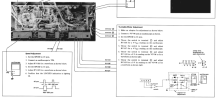
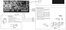
Hey so you mentioned to do the p-p first but I am puzzled by what it is asking to do- what does the Turntable motor adjustment below mean by #1- Make an adapter? and then to throw the switch to terminal 5 and 6? Is it meaning to create a jumper coming off of the circuit between those 2 diodes (which I can't find on the board), and then attach the probe to the jumper wire? Then connect the positive lead to a resistor? Very confusing to me.


1745283420415.png
 
That adapter is supposed to help you set 0 offset. It makes a DC voltage of the 2 half waves which it adds and if centered would yield 0V on a DMM with that circuit. What I did was power the TT and look at pins 5 and 6 (I found it easier to clip leads on the E pins of the output transistors. Don't make the mistake that I did - running the turntable at an angle to get to things overloaded my transformer - and it effects these readings. So power on and set you volts/div to 100mV and make sure the emitters (5 and 6) both read 0. Then go to 1V/div and run the platter. The peaks should be 2 blocks above and below the center for 4V pk to pk. I slid the TT off the table to adjust these while running - one at a time.

For the speed adjustment, keeping to the higher time window (250uS and 550uS) is better I found. When running, the square wave on your scope should be pretty stable. This is the servo adjusting for every clock from the magnetic reader (284Hz). I couldn't improve it's stability adjusting gain or offset so I don't know if it's possible for it to be a perfectly stable signal.

My CX193 was bad and once replaced, I have WOW at 0.05% to 0.07% using the RMS WOW app. Speed was 0.07% accurate and slightly low on average. Moving the speed adjust to the higher end helped to increase the speed but there's a fine line to suddenly having the wave become unstable or it flipping upside down. It is a super sensitive adjustment. Seeing that it's so touchy and I had worn out the original pots with months of testing with a bad CX193, I replaced those pots and redid the speed adjustment. The new pots had much more friction which made them a little harder to set but I know that they won't move from temperature changes.

Can I ask, when yours is powered for a while, is the heat sink on the main power supply pretty darn hot? Like too hot to touch? (which I know for electronics is not a bad indication). I feel like there's not much in there to draw current to throw off that much heat. I'm all buttoned up and was listening to albums finally after 5 months. It's rewarding to have fixed it.

 
That adapter is supposed to help you set 0 offset. It makes a DC voltage of the 2 half waves which it adds and if centered would yield 0V on a DMM with that circuit. What I did was power the TT and look at pins 5 and 6 (I found it easier to clip leads on the E pins of the output transistors. Don't make the mistake that I did - running the turntable at an angle to get to things overloaded my transformer - and it effects these readings. So power on and set you volts/div to 100mV and make sure the emitters (5 and 6) both read 0. Then go to 1V/div and run the platter. The peaks should be 2 blocks above and below the center for 4V pk to pk. I slid the TT off the table to adjust these while running - one at a time.

For the speed adjustment, keeping to the higher time window (250uS and 550uS) is better I found. When running, the square wave on your scope should be pretty stable. This is the servo adjusting for every clock from the magnetic reader (284Hz). I couldn't improve it's stability adjusting gain or offset so I don't know if it's possible for it to be a perfectly stable signal.

My CX193 was bad and once replaced, I have WOW at 0.05% to 0.07% using the RMS WOW app. Speed was 0.07% accurate and slightly low on average. Moving the speed adjust to the higher end helped to increase the speed but there's a fine line to suddenly having the wave become unstable or it flipping upside down. It is a super sensitive adjustment. Seeing that it's so touchy and I had worn out the original pots with months of testing with a bad CX193, I replaced those pots and redid the speed adjustment. The new pots had much more friction which made them a little harder to set but I know that they won't move from temperature changes.

Can I ask, when yours is powered for a while, is the heat sink on the main power supply pretty darn hot? Like too hot to touch? (which I know for electronics is not a bad indication). I feel like there's not much in there to draw current to throw off that much heat. I'm all buttoned up and was listening to albums finally after 5 months. It's rewarding to have fixed it.
OK, are you stating that you bypassed making this adapter and just connected straight to pins 5 & 6 to make the adjustments? If not, how did you go about making this adapter?

Also, I have not noticed extreme heat from the PS sink. I'll check that tonight while testing.
 
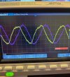
Yes I didn't make the adapter and did it as outlined in my previous post watching pins 5 and 6. They should be 0V or close to it when you power up. Using 100mV/div helps really to see 0V. If not, spin the platter and ensure the peaks of the sine wave are covering the same number of horizontal lines. Note that the sweep has to be very slow because the output sine wave is a low frequency (as scopes go). You should still be able to tell that the waves are centered. The sine waves are not lined up but offset.
 
Your output should be something like this. I did increase the yellow just a tad as it's peak to peak was a bit low when I snapped this. Notice it is as centered (0 offset) as I sure can tell. If you want the speed test point video I can show that too.
 

Attachments

  • Sony_Scope.JPG
    Sony_Scope.JPG
    131.1 KB · Views: 5
Back
Top Bottom