• The move to the new server is done. There are some software and database maintenance updates in process. This has us passing the hat around to help out. We appreciate any donations. Seriously, even a dollar helps. The payment page may be found here - https://www.audiokarma.org/support.html

Sony STR-7035 FM issues

MattiaM

Active Member
I have been recently working on a Sony STR-7035 with a number of issues.
The FM tuner appeared to have very little reception, picking up only one very strong local station. I figured it was misaligned, and after a quick alignment of the IF section, it worked much better.
However, there are still issuess, one of which seems to be related to muting.
When muting is on, I get no reception at all; when off, I do get stations, but it appears as if the muting was on, with no noise between stations. Even with strong stations, there is almost no deflection of the signal meter. Unfortunately the only signal generator I have has a max frequency of 25MHz (the service manual calls for a 1uV 93MHz unmodulated for the muting and signal meter), so I cannot check whether the muting levels are set correctly, and I guess they are not. However, that does not seem to be the only problem: looking at the schematics, the muting acts on the gate of the Q304 FET, with 0V if muting is active, and some positive voltage when muting is off. This works fine, and when muting is off I measure about 4.1V. The drain shows 4.3V, close enough to the correct values. The source shows about 3.7V when the muting switch is ON, and 4.3V when off, whereas it should measure 1.8V; I have been checking everything, but I don't seem to be able to find out why I get that wrong voltage. All the resistors (R333, R334, R335, and R252) are in spec; I replaced C303, the 15.4V rail measures good and the FET tests good with a basic component tester. Does anyone have any guesses about the possible cause?
That does not seem related to the muting part of the circuit, because that should only affect the gate of Q304

Thanks.

FM-muting-stereo.JPG
 
Register to hide this ad
You really need to have the proper RF test equipment to troubleshoot this. It is losing gain somewhere, could be in the front end, could be in the IF. You need a high impedance active RF probe that will not load the circuits, a generator that will go to 108 MHz, and at minimum a scope with 200 MHz bandwidth. I use a spectrum analyzer. Now, you can try to use an RF detector probe that demodulates RF into a varying DC voltage but then you don't really have any way of knowing what you are looking at.
 
I don't think that the issue is the loss of gain in the various amplification stages of the front end or IF; after aligning the IF sections, the tuner picks stations well, comparable with other receivers I have around. I do agree that without at least a signal generator with a higher max frequency I can't fix the muting issue and set the signal strength meter properly, but I don't think anything from Q207 and right should affect the wrong voltages I see at the source of Q304 :idea:
 
I don't think that the issue is the loss of gain in the various amplification stages of the front end or IF; after aligning the IF sections, the tuner picks stations well, comparable with other receivers I have around. I do agree that without at least a signal generator with a higher max frequency I can't fix the muting issue and set the signal strength meter properly, but I don't think anything from Q207 and right should affect the wrong voltages I see at the source of Q304 :idea:
I think you're looking at the wrong thing. Don't worry about the DC voltages on Q304, it's passing the AC signal from the discriminator. The Drain is the output. You should have audio on the Source and Drain unless it's muting. Ideally you should have proper test equipment to align the discriminator properly for 0V on the output when it's properly tuned with max signal and minimum distortion. Then, at that point you peak IFT202 for max signal strength and the muting should work. Since you don't have proper test equipment the safest thing to do is tune in a station for max signal strength and center tuning, then adjust IFT202 to the middle of the range where the stereo lamp lights. That will get you close.
 
Last edited:
Thanks for your suggestions.

I did a bit more testing, and it turns out you were indeed correct saying that there must be a loss of gain somewhere. I finally used this repair as an excuse for getting a proper signal generator (Panasonic VP-8193A) and learn a bit more about alignments.
The first thing that I found was that, when lighlty coupling the signal for the IF alignment to the tuning capacitor as from service manual, I would need to push the output of the signal generator to about 1V (modulated with a 400Hz 30% modulation signal) to be able to see any AM and to zero it. In FM, that 120dBuf modulated with a 400Hz signal would give me about 300mV peak to peak across C217. Injecting the signal to the FM antenna, I could only get any output with signals way too high: A 120dBuf signal would give me a 4 (out of 5) signal strength reading on the signal meter, whereas I am supposed to get almost max deflection with around 1mV. I would start seeing something on the scope at about 70-80dBuf, which is a really high signal.
I did manage to zero the AM signal and peak IFT101, so I will try and see what's going on in the front end. Unfortunately the manual there does not provide any instructions there for the RF alignment other than frequency coverage, which is OK in my case.
 
It turns out it was the base-to-emitter of Q201 that was open. Once I replaced it, I got a very good reception, I could do a good IF alignment and the muting and signal meters are now woking and in specs. The only issue now is the stereo lamp switch, that does not seem to work.
 
I am again at a dead end: I seem to have two issues: one is that Q303 never turns on. The max base voltage I seem to get is 0.3V. The second issue is that the collector of Q302 sees always about 7.7V, regardless of the position of the mono switch, instead of the 14.5V that are supposed to be measured when Q302 is off. Given that Q303 never turns on, Q302 is always off. I have the right voltages in the supply, I replaced all electrolytic caps, and I checked all the resistors (R322,323,324, 325, 312, 317 and 318) and they are all in specs. I measured these voltages with the stereo lamp disconnetted; if connected, it's unsurprisingly on all the time. Could that current draw be caused by something wrong with L302, the secondary windings in particular?
 
I did more testing on the stereo section, and this is what I found:

I do not seem to get stereo, all the adjustments are unresponsive (apart from RT501), Q303 (38kHz amplifier) appears to always be off, regardless of the strenght of the incoming signal, and the collector of Q302 shows always a wrong voltage of 7.7V DC.

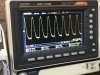
I checked all the transistors, resistors and capacitors in this part of the circuit, and they all work and are in spec. I replaced all the electrolytic caps just in case. If I inject a 19kHz signal from an audio generator directly to the base of Q301, I get an amplified signal at the collector; I also get a very very noisy 38kHz signal at the cathode of D301 and D302 (see first scope trace attached). Regardless of the amplitude of the injected signal (up to a few volts), I can only get a maximum DC voltage of about 0.63~0.65V at the base of Q303, from a 200-300mV with no signal and about 20-30mV with the stereo switch in the mono position; nowehere near the 2V that I should be able to see.

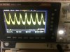
If I use the pilot signal from the RF sig. gen. injected to the antenna terminals on a 93MHz carrier, I can't see any decent 19kHz signal downstream of the detector, but I see a very weak very noisy signal (80mV pk-to-pk), almost impossible to trigger on the scope (second scopet trace attached). If I crank up the signal to the antenna I end up triggering the scope on the RF carrier leaking through the detector. I have now run out of ideas. I even tried looking at the frequency response of the front-end and IF stages, and there is a lot of filtering going on: a carrier FM modulated with a 400kHz signal (I think I set it at 60dBuV) gives me a 400mV peak-to-peak at the detector, but 200mV with a 4kHz modulation, and it carries on going down as I increase the frequency, to nothing visible at 19kHz.

Does anyone have any idea on the possible issue, or what else to check and try?

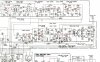
Attached are the section of the circuit, the 38kHz signal at the cathodes of D301-D302 when I inject a 19kHz signal at the base of Q301, and the same when I use the pilot tone modulating a 93MHz carrier injected to the antenna.
Capture.JPG IMG-4798.jpg IMG-4807.jpg
 
How does it *sound*? Do the highs sound muted?

Looks like MU301 is not adjustable. Put the scope on the collector of Q301, and inject that 19 KHz signal a bit earlier on, say at C303 to avoid disrupting Q301 operating conditions. Use only enough signal to get a usable display on the scope. Sweep the input frequency and find where the output you see on the scope peaks. Trying to determine where MU301 is actually resonant.
Now look at the emitter of Q301. You should see a notch at 19 KHz.
 
Put the scope on the collector of Q301, and inject that 19 KHz signal a bit earlier on, say at C303 to avoid disrupting Q301 operating conditions. Use only enough signal to get a usable display on the scope.

At the collector I get the peak at 19.1kHz, it's fairly flat between 18.5 to 19.6 kHz and then drops steeply below and above. Sounds good to me.
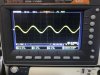
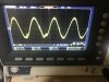
At the emitter, I get a very nice looking pattern (see first picture), from 18.6 to 19.1kHz. above and below I get a sinewave (second picture). Is that what I can expect from the notch? I was expecting a flat trace. I could have tried the FFT but did not think of that yesterday evening when I did the test.
Injecting the signal earlier has removed pretty much all the noise I was seeing. I didn't know the effect could be so large. The third picture shows the signal at the cathode of of D301 and D302: much much cleaner than the erlier ones.

In terms of how it sound, funny how often we miss the simplest things. In all my testing I never did an actual listening test. I now hooked up the receiver to some speakers, and reception is very good, much better for example than a Sansui G-4700 that I use regularly. Strange thing, it definitely has stereo reception, but it's not well balanced with the left channel slighlty stronger (this isn't a problem of the amp section). Another thing, it sounds slighlty noisy even with very strong signal, and with some perceivable distortion, suggesting it is not well aligned after all.

It really puzzles me why I don't see the right base voltages at Q303 and the whole on-off switch when a stereo signal is applied, and where the fixed 7.7V at the collector of Q302 comes from, especially given that stereo from listening works fine indeed.
One thing is sure: I did something wrong when I tested stereo originally, becasue I got equal sign amplitude in both channels regardless of how I would set the stereo generator (L+R, L, or R). It could be just a stupid mistake like the mono switch on. I will try again later.

IMG-4822.jpg IMG-4823.jpg IMG-4825.jpg
 
You have almost 6V p-p of 38 KHz and the diode cathodes. If you DC couple the scope, I would expect that waveform to be almost all above ground giving a nominal DC voltage of almost 3 volts. That DC is coupled through R308 and R310 to the base of Q303. R310 is a 56K, but the base current of Q303 shouldn't draw much current, so I would not expect a *huge* drop across it. Might want to check C309 for leakage or Q303 for low hFE.

To back up a bit, the composite audio path is through the emitter of Q301. The series LC circuit connected to the emitter would be resonant at 19 KHz, which serves the dual purpose of bypassing the emitter at 19 KHz, giving the amp more gain, and reducing the amount of 19KHz that is passed along with the composite audio to the demux. That waveform (pix 1) is a bit strange, but now too concerning.
 
Looking a pix 3, I am wondering why there are two different waveforms superimposed. Almost as if one of the waveforms is harder drive than the other. Might want to check D301 & D302 just for grins.
 
Looking a pix 3, I am wondering why there are two different waveforms superimposed. Almost as if one of the waveforms is harder drive than the other. Might want to check D301 & D302 just for grins.

That could be the fact that one of the two diodes was shot, and I replaced it with an NTE109; I only had one in stock and I am waiting for the new ones to show up in the mail.
It could also be (maybe? I am not sure about this) the fact that the bottom half what comes out of the detector is not very clean (that is where my distortion comes from).

IMG-4809.jpg
 
What is the purpose of the part of the circuit connecting C310, R312, R317, the Center two of the secondary of L302 and R318 to ground?

I’m asking because I still have issues with the stereo lamp, which is constantly on, dimmed when there’s no stereo signal, and now strong with stereo. If I remove R312, all works fine, voltages are as per manual and the stereo lamp only lights up when there’s stereo signal.
 
This is the path the composit audio follows to the decoding matrix. If everything is working properly, when receiving a stereo signal the collector of Q302 is very near ground, so the DC voltage seen at the CT of L302 is about zero. When no 19 KHz is seen, Q302 collector goes high and that DC voltage is coupled through to the CT of L302, forcing the decode diodes to the on state allowing the mono audio to pass. Without R312, the audio on a mono station will likely be distorted.

Check C310 for leakage. Is the stock incandescent lamp in there for the stereo indicator or has it been replaced with an LED?
 
thanks for that explanation, that makes a lot more sense now.
I replaced C310 earlier on, and rechecked now, and it is OK.
The stereo indicator has been replaced with an LED and a 750Ohm resistor in series; I removed it, and I measure 7.8V at the collector of Q302; there is 1mA going across R324 and R312. If I remove C310, same voltages. Could the issue be a leaky diode (D305 or D306)?
 
I removed it [the LED?], and I measure 7.8V at the collector of Q302
The circuitry is looking for the current through the stereo indicator bulb in both stereo and mono modes. The original bulb is rated at 4.5 volts 40 mA, and the circuit appears it would be pushing about 30 mA though it. Replacing it with an LED reduces that current considerably (to about 10 mA). I would suggest changing the LED series resistor to 470 ohms, and adding a 470 ohm resistor in parallel with R324, or just replace R324 with a 470 ohm resistor.

After that change, you should see, in mono mode:
About 13-14 volts on the collector of Q302, and 0.0 mA through the LED.

In stereo mode:
About 0.1 volts on the collector of Q302, and about 10 mA through the LED.

See if that config works better.
 
Thanks so much for taking the time to explain this. I followed your suggestions, and the circuit works great.
So basically, my mistake was to assume that no light: no current through the lightbulb.
A question: without the specs of the lightbulb, was there going to be a way to figure out all the currents/voltage drops in stereo and mono?
 
I have been recently working on a Sony STR-7035 with a number of issues.
The FM tuner appeared to have very little reception, picking up only one very strong local station. I figured it was misaligned, and after a quick alignment of the IF section, it worked much better.
However, there are still issuess, one of which seems to be related to muting.
When muting is on, I get no reception at all; when off, I do get stations, but it appears as if the muting was on, with no noise between stations. Even with strong stations, there is almost no deflection of the signal meter. Unfortunately the only signal generator I have has a max frequency of 25MHz (the service manual calls for a 1uV 93MHz unmodulated for the muting and signal meter), so I cannot check whether the muting levels are set correctly, and I guess they are not. However, that does not seem to be the only problem: looking at the schematics, the muting acts on the gate of the Q304 FET, with 0V if muting is active, and some positive voltage when muting is off. This works fine, and when muting is off I measure about 4.1V. The drain shows 4.3V, close enough to the correct values. The source shows about 3.7V when the muting switch is ON, and 4.3V when off, whereas it should measure 1.8V; I have been checking everything, but I don't seem to be able to find out why I get that wrong voltage. All the resistors (R333, R334, R335, and R252) are in spec; I replaced C303, the 15.4V rail measures good and the FET tests good with a basic component tester. Does anyone have any guesses about the possible cause?
That does not seem related to the muting part of the circuit, because that should only affect the gate of Q304

Thanks.

View attachment 1924397
I know I'm late to this string but the info offered here is very thorough and detailed. Nice work...... I have been researching many of the issues noted above and came across this YT video from an absolutely excellent presenter.... For those of us who are not electronic engineers this is a great video with many nuggets so pay attention..... For those who are engineers or already skilled in the art of saving these amazing relics from bygone days, the techniques used can refresh your troubleshooting skills. For me, it saved a lot of time and frustration as it details not only what the issues are but how to go about fixing them, especially the issue with the stereo bulb; aka mono-only issue on a Sony str chassis. For troubleshooters everywhere, Enjoy.
 
Back
Top Bottom