

You are using an out of date browser. It may not display this or other websites correctly.
You should upgrade or use an alternative browser.
You should upgrade or use an alternative browser.
Sony STR-7035 no fm stereo
- Thread starter sruchris
- Start date
Register to hide this ad

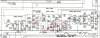
R309 to ground is measuring between +0.1mv and +0.3mv as I tune across the dial. It never gets higher than +0.3mv even when tuned to a strong station. The voltage does drop to -0.5mv when I press in the mono button. Enabling the FM muting button doesn't change the voltage.

Ylli
Super Member
So you are getting no output from the 19KHz to 38 KHz doubler. Let's back up a stage and measure the voltages.
With the 'Stereo - Mono' switch set to Stereo,and the 'FM Mute' switch to 'Off':
Q301 collector -
Q301 base -
Q301 emitter -
From your description I am assuming that: Mono reception is OK, and that if the 'FM Mute' switch is set to 'On', that the receiver mutes between stations and comes back alive when tuned to a station. I am assuming the Signal Strength meter is active. If the above is not true, let me know.
With the 'Stereo - Mono' switch set to Stereo,and the 'FM Mute' switch to 'Off':
Q301 collector -
Q301 base -
Q301 emitter -
From your description I am assuming that: Mono reception is OK, and that if the 'FM Mute' switch is set to 'On', that the receiver mutes between stations and comes back alive when tuned to a station. I am assuming the Signal Strength meter is active. If the above is not true, let me know.
Ylli
Super Member
So the Mono audio is passing through Q301 (in the base, out the emitter) and the biases on the transistor look OK. The transformer in the collector circuit along with diodes D301 and D302 form a frequency doubler, and there should be 38KHz and a DC component at the junction of D301 and D302 cathodes. We are not seeing that DC component. I am fearing you may have a bad transformer MU301.
Do you have access to a oscilloscope?
Assuming no, then lets try to eliminate as much else as we can. You will need to lift the cathodes of D301 and D302.
(With power off) Measure the resistance between D301 Anode and ground, then do the same for D302. Should be near zero ohms. (checking transformer secondary for continuity)
Using the 'Diode' function on you meter, test D301 and D302 (if you don't know how to do that, ask).
Tie the cathodes of D301 and D302 together and connect your volt meter between that junction and ground. Turn the receiver on and see if you can get any DC voltage at that point.
Do you have access to a oscilloscope?
Assuming no, then lets try to eliminate as much else as we can. You will need to lift the cathodes of D301 and D302.
(With power off) Measure the resistance between D301 Anode and ground, then do the same for D302. Should be near zero ohms. (checking transformer secondary for continuity)
Using the 'Diode' function on you meter, test D301 and D302 (if you don't know how to do that, ask).
Tie the cathodes of D301 and D302 together and connect your volt meter between that junction and ground. Turn the receiver on and see if you can get any DC voltage at that point.
I don't have an oscilloscope. I lifted the cathode legs of D301 and D302 and here's what I got
D301:
37 ohms (- to ground, + to anode)
0.21vdc forward bias
OL reverse bias
D302:
40 ohms (- to ground, + to anode)
0.23vdc forward bias
OL reverse bias
With the cathodes tied together and the receiver on, I'm getting 9.6mv.
D301:
37 ohms (- to ground, + to anode)
0.21vdc forward bias
OL reverse bias
D302:
40 ohms (- to ground, + to anode)
0.23vdc forward bias
OL reverse bias
With the cathodes tied together and the receiver on, I'm getting 9.6mv.
Last edited:
Ylli
Super Member
Go ahead and solder D301 and D302 back into the circuit so they don't get broken.
Transformer secondaries have higher resistance than I expected, but they are not open and they are about the same - which says the secondary is OK. Given that Q301 collector is at +15.4 volts, the primary of the transformer is not open. Diodes are good. That leaves the tuning capacitor internal to MU301. I have worked some threads where that cap has failed.
I see two options...
1. Try to find a replacement transformer.
2. Try using an external capacitor.
In regard to #2, Is there a actual pin through the board at the indicated position on MU301? Or is it just a blank pad on the back of the board?

Transformer secondaries have higher resistance than I expected, but they are not open and they are about the same - which says the secondary is OK. Given that Q301 collector is at +15.4 volts, the primary of the transformer is not open. Diodes are good. That leaves the tuning capacitor internal to MU301. I have worked some threads where that cap has failed.
I see two options...
1. Try to find a replacement transformer.
2. Try using an external capacitor.
In regard to #2, Is there a actual pin through the board at the indicated position on MU301? Or is it just a blank pad on the back of the board?


Ylli
Super Member
These two pins should be the connections to the internal capacitor:

The attempted fix would be to solder an external disc capacitor between these two pins. You would need to have a selection of values available: 33pF, 39pF, 47pF, 56pF, 68pF, 82pF, 100pF would represent the range I would expect the internal cap to be.
Method would be to tack the 68pF cap across these two pins, then turn the unit on and check the voltage either end of R309 to ground. Hopefully you will see something more than a few mV. Then try an adjacent value cap (56pF or 82pF) and see if the voltage increases or decreases. Find the cap that maximizes the voltage. (If you find you need to go above 100pF, you can just parallel two caps - the value of parallel caps simply add).
Is there an adjustment slug accessible on the top of this transformer - on the side we are working with?
The attempted fix would be to solder an external disc capacitor between these two pins. You would need to have a selection of values available: 33pF, 39pF, 47pF, 56pF, 68pF, 82pF, 100pF would represent the range I would expect the internal cap to be.
Method would be to tack the 68pF cap across these two pins, then turn the unit on and check the voltage either end of R309 to ground. Hopefully you will see something more than a few mV. Then try an adjacent value cap (56pF or 82pF) and see if the voltage increases or decreases. Find the cap that maximizes the voltage. (If you find you need to go above 100pF, you can just parallel two caps - the value of parallel caps simply add).
Is there an adjustment slug accessible on the top of this transformer - on the side we are working with?

David_NC
Super Member
I have an STR-7055 with this same issue. From what I've read online, there's an IC that goes bad and is, unfortunately, unavailable except from scrap units. I'm not sure if the entire STR-7xxx line has this tuner design or not. I haven't investigated it in my unit, but I'll check back here in case there's a solution.
Ylli
Super Member
The '7055 has a totally different MPX section. Always best to start a new thread for a new problem.I have an STR-7055 with this same issue. From what I've read online, there's an IC that goes bad and is, unfortunately, unavailable except from scrap units. I'm not sure if the entire STR-7xxx line has this tuner design or not. I haven't investigated it in my unit, but I'll check back here in case there's a solution.
David_NC
Super Member
I wasn't asking for advice but merely offering a possible suggestion based on a problem with my unit that also exists in other models of this line. I do start new threads when needed, but thanks.The '7055 has a totally different MPX section. Always best to start a new thread for a new problem.

While I don't have a big selection of small ceramic caps here, I did find a 40pf and a 120pf. I attached each one individually to the pads in the photo. Each one gave me the same result: 0.0mv on both ends of R309 when tuned to a strong station and it goes up to 3.0mv when in between stations. The red plastic case of the transformer at MU301 is sealed with no adjustments.
Ylli
Super Member
Doesn't sound to promising, Sorry, I have no other suggestions to offer.While I don't have a big selection of small ceramic caps here, I did find a 40pf and a 120pf. I attached each one individually to the pads in the photo. Each one gave me the same result: 0.0mv on both ends of R309 when tuned to a strong station and it goes up to 3.0mv when in between stations. The red plastic case of the transformer at MU301 is sealed with no adjustments.
Ylli
Super Member
No offense intended.I wasn't asking for advice but merely offering a possible suggestion based on a problem with my unit that also exists in other models of this line. I do start new threads when needed, but thanks.
Nope. I still have the stereo though.Hi did this ever get sorted