• The move to the new server is done. There are some software and database maintenance updates in process. This has us passing the hat around to help out. We appreciate any donations. Seriously, even a dollar helps. The payment page may be found here - https://www.audiokarma.org/support.html

SONY STR-7055 - NO OUTPUT - DC OFFSET & BIAS Values WAAAY out of spec.

toymanmsp

Active Member
Greetings all, I'm rebuilding my 7055 but am in need of some HELP!! I am a novice/newbie to rebuilding vintage gear. That said, I have successfully rebuilt several Pioneers and Sansui's but this is my first go with a piece of SONY gear. I love the looks and particularily the sound from this receiver and am planning to rebuild it. I'm aware that this series of receivers has heat issues with the Power Supply boards. I have replaced all the caps on the power supply board, along with the two main filter caps the receiver powers on but I am getting no output from either channel which is odd as this wasn't an issue between replacing the main filter caps and testing (has output) and then moving onto the PS board??? I have not replaced anything other than the caps (I did replace the lamps with LED's) and checked and rechecked that the caps have been installed in the proper orientation (I am planning on replacing the 11 diodes, 18 transistors, 2 zeners, VD1212 diodes with 2x1N4148's on the PS board and the 3 large resistors). I am reading -1.3 mv / -1.2 mv on my bias adjustments, but when the trimmer is being adjusted there is not change to the mv reading and am unable to set to the correct 50 mv reading. My DC offset reading is way off as I'm reading a -1.9 V vs. mv's, so something is not right.

A couple of outliers, if the volume turned all the way up and set to FM, I can hear crackling in both channels, when I select AUX with an iPod I hear nothing. I did hear static/crackling when set to the AUX function with an iPod in both channels again with the volume cranked. I then cleaned the pots and switches, and now only have the crackling/hiss on FM. This was thru a pair of headphones and not from the speaker outputs.

So, I'm in need of some direction or assistance. I'm guessing that this is either an issue with the input transistors being out of spec and/or the output transistors are blown or perhaps and issue with the pre-amp? A bit of a shot in the dark. I'm thinking as a next step of testing the output transistors, but not sure if this would be an appropriate next step? Any input would be appreciated. Thanks.
 
Register to hide this ad
Thanks for the quick reply, late night for you. This is where I get challenged is reading the sm and schematics correctly. :) I'll let you know what I find out. Thanks, Pete
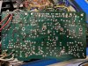
Ok, I figured out what the issue was and have sound coming from both channels. When I replaced the main filter caps, the new screw holes were larger than the original, so I replaced the connectors, but didn't get good contact on all the wiring to the connectors. Reworked them, and seem to be good to go.
 
Great that you resolved it!

I'm a little curious why the shtogun replacement of diodes and transistors. Is something wrong with them? Unless there is, the only items among those that might need a closer look are probably the couple of transistors that are on the list on this forum (there are a couple that might lose gain), and - if your DC offset is high - replace the differential pairs with hFE matched pairs.

There are one or two fusible resistors on the power supply board that would be a good idea to replace (be sure to stand them off adequately for cooling) and give a visual check to be sure there's no physical damage to any of the other resistors on that board.

Multi-turn trimpots can be a nice upgrade, to help make fine bias adjustment easier, but are not essential and will probably require extending the leads to reach the holes.

Before buttoning it back up, do your best to gather the wiring above the power supply section of that board to allow the best possible convective air flow.
 
Well, I thought that I had this resolved with the output and the filter caps. I've installed new caps (Panasonic FC) all oriented correctly on the PS Board. I've replaced the transistors systematically, one by one, replace turn-on, test, and repeat. I believe all oriented correctly, BUT, I'm not getting a strong output from the right channel, which I'm finding strange as I'm getting a very strong left channel output (sounds great),. So, I either have transistors installed incorrectly or would it be possible that I have a blown output transistor on the left channel? The interesting part is that I know that the large resistors should have a high-temperature level and all three are running at 76 degrees, well below the 100+, same for the transistor with heatsink, that I've read previously with my digital thermometer. I did have one of the white lead come off the board leading to the power transformer, but have resoldered and appears to have good contact on the board. Fuses look good. I'm assuming that I'm not getting any power to the large resistors that there is an issue with the PS board. I've done NO other work on the receiver other than the board. I realize that I need to get the voltages settled, but am at a bit of a loss at the moment.

Other items to note, I've cleaned all pots and switches multiple times, the source setting is set to source. I have had 3 resistors that have singed but are not out of spec. I've replaced them. I also replaced the 20 ohm resistor (which I believe was the fusible resistor on the board, it was reading 10 ohms). Have tried to set bias am still having issues with being able to set this to the 50 mv, I get no readings when I try to adjust. I have replaced the differential pairs hFE matched, but still no change to setting the bias. I do have replacement trimmers which I had/have planned to install, just want to get a sanity check.

Lastly, would anyone have a picture of a rebuilt board as a comparison to what I've done on my board? Suggestions, advice, comments (please be kind) are welcome.

Thanks.

Also, only getting output from the aux input no FM. Have'nt tested the Phono input.
 
Last edited:
Great that you resolved it!

I'm a little curious why the shtogun replacement of diodes and transistors. Is something wrong with them? Unless there is, the only items among those that might need a closer look are probably the couple of transistors that are on the list on this forum (there are a couple that might lose gain), and - if your DC offset is high - replace the differential pairs with hFE matched pairs.

There are one or two fusible resistors on the power supply board that would be a good idea to replace (be sure to stand them off adequately for cooling) and give a visual check to be sure there's no physical damage to any of the other resistors on that board.

Multi-turn trimpots can be a nice upgrade, to help make fine bias adjustment easier, but are not essential and will probably require extending the leads to reach the holes.

Before buttoning it back up, do your best to gather the wiring above the power supply section of that board to allow the best possible convective air flow.

Hi 50 Green, regarding your question, I've done this on prior power supply boards (primarily my Pioneers) I have held off on any replacements per your comments. I've replaced the known bad transistors along with the differential pairs. I'm at a bit of a loss, am leaning towards testing the output transistors? But will wait until I get some input from the forum. Thanks for your input and suggestions. I've seen your other posts and you have offered great input. I appreciate your reply. Any insight you have would be helpful. Thanks!!
 
Hooked up my Marantz 240 power amp to the preamp moved the selector switch to the separate setting (vs. Normal) getting output from both channels, but only on AUX sounds stellar, but still no FM. Really don't know how to interpret this? Is the issue only isolated to the PS or something completely different. Back to thinking about the main filter caps. Dunno?
 
You'll have a much better chance of resolving issues if you stop randomly replacing parts and begin careful, methodical diagnosis. It's a little difficult to follow your narrative but it appears you're saying that input via AUX plays fine through an external power amp. This would eliminate any power supply issues, at least with the preamp section. As for good sound via AUX only, note that the FUNCTION switch on these units can cause partial, and even complete, channel drop out if its contacts are dirty or oxidized. This switch is a combination rotary / slider switch. It's easy to clean the rotary section and miss the slider. Even if you have cleaned the slider, you may not have done it completely. It is difficult to get contact cleaner into the area where the contacts are. The slider needs to be positioned right for the best access to the contacts and you need to find a suitable entry point for the contact cleaner. (Looking at the pinout on the bottom of the board can help determine where the contacts are.) After cleaning, it's necessary to lubricate it (with Faderlube or something similar.)

One more note: the differential pairs have no bearing on bias setting. They control DC offset only.

If you post clear photos of what you've done, they may help others to help you.
 
You'll have a much better chance of resolving issues if you stop randomly replacing parts and begin careful, methodical diagnosis. It's a little difficult to follow your narrative but it appears you're saying that input via AUX plays fine through an external power amp. This would eliminate any power supply issues, at least with the preamp section. As for good sound via AUX only, note that the FUNCTION switch on these units can cause partial, and even complete, channel drop out if its contacts are dirty or oxidized. This switch is a combination rotary / slider switch. It's easy to clean the rotary section and miss the slider. Even if you have cleaned the slider, you may not have done it completely. It is difficult to get contact cleaner into the area where the contacts are. The slider needs to be positioned right for the best access to the contacts and you need to find a suitable entry point for the contact cleaner. (Looking at the pinout on the bottom of the board can help determine where the contacts are.) After cleaning, it's necessary to lubricate it (with Faderlube or something similar.)

One more note: the differential pairs have no bearing on bias setting. They control DC offset only.

If you post clear photos of what you've done, they may help others to help you.

Hi, 50 Green thanks for the message. Sorry that the narrative is difficult to follow, dealing with an ADHD brain that is always on the move. The diagnosis is the challenging part for me as I'm still new and learning. Sequence of events this morning,

After cleaning the Function switch, I powered on the receiver and still only get the left channel, however, when I adjust the balance to the left I can hear the left channel. When I move the balance to the right, I hear the right channel, where I shouldn't hear the left channel. The rear switch is set to normal. I get this and both speakers plugged in and the same if the right speaker is unplugged. Tested with headphones and do get a separation of the channels when adjusting the balance, but there is a good deal of static on both channels particularly the right channel. I've cleaned both the volume and balance pots several times but will give another pass on these as well.

Treated the function switch again this morning with D5 and F5 and hooked up the 240 and I have phono on both channels but NO FM signal (with antennae connected). Removed the 240 and set the rear switch back to normal and now when I adjust the balance I'm getting only the left channel output when turning to the left channel and no sound when I turn to the right channel. This receiver seems to have a mind of its own this morning.

Also, when moving thru the function switch quickly rotating I did hear a brief output from the right channel and then faded (maybe a 1 second of garbled sound). Regarding the differential pairs, I misspoke. I still, however, can't adjust the bias, which I'm assuming means that there is still an issue with the power supply? I do get the left channel on phono like the AUX input when set to normal, but again NO FM signal.

Also, the larger resistors are not generating any heat I can touch all of them with a finger, so again, I'm assuming that this still leaves me with a power supply issue.

Finally, I did notice that there is a crack in the board on the lower left-hand corner of the power supply board, I've checked the continuity of the circuits and do have continuity. I'm not sure if this was there prior to me picking up the receiver. Now, to figure out where to go from here...Thanks again for the reply. Hopefully, this makes more sense.
AE7EFB95-52C8-4A94-B940-08C982EC78E4.jpeg7A28F684-447E-465B-A83A-15908BD65165.jpegA90704D8-7F9D-4E93-879F-A18E34C2B5E4.jpeg01131DF8-8546-467E-8A17-868CA1EF62F4.jpeg190122C8-8830-4102-BE40-C19C3B2D4EA3.jpegA39A68B3-B336-4C4E-8389-4252B629E5AE.jpeg
 
Question 1: Did this receiver function correctly before you started any work on it?

Question 2: Did you check voltages, as petehall347 recommended?

Bias not adjusting should not be a power supply issue, unless the outputs are not getting power. If you have not checked voltages already, you can start by checking the voltage at the ORANGE lead at the top of the PS/Amp board. With the power off and using minigrabbers, connect the red lead from your DMM to the ORANGE lead on the board, and the black lead on your DMM to the metal of the chassis. Turn on the receiver and check the reading. It should be 50V. Next check the WHITE/BLUE lead on the same board, in the same way. With the power off, and using minigrabbers, connect the red lead from your DMM to the WHITE/BLUE lead on the board, and the black lead on your DMM to the metal of the chassis. Turn on the receiver and check the reading. It should also be 50V. USE MINIGRABBERS FOR THIS. IF YOU DON'T OWN ANY, BUY A PAIR BEFORE YOU TAKE THESE READINGS. If both of these readings are 50V (or close) your power supply is OK and you can consider further, methodical, checks.

The crack in your PS board does not appear to affect any traces. There are some lines higher up on the same board. I can't tell what exactly they are, but you might double check to see whether the traces are damaged in any way.

There appear to be some solder bridges on that board. Check to be sure they are not bridging in places the traces don't bridge. (Also, clean your flux residue off!)

I'm not sure what you're saying about the left and right channels. I read that you hear the left channel when the balance is to the left and the right channel when the balance is to the right. That's how it's supposed to be, so if something is not as it should, could you describe what it is?

The volume/balance is a 4-gang pot. Did you clean all four? (One is a little difficult to get to, and more easily accessed if the nut securing the pot is removed, and the pot pulled back a little from the front mounting plate.

What parts of the FUNCTION switch did you clean, and how?
 
Hi 50 Green, Thanks for your message. Apologies for the delayed reply. I appreciate the detailed steps below.

Question 1: Did this receiver function correctly before you started any work on it?

Yes, the receiver functioned correctly but did have some distortion in both channels.

Question 2: Did you check voltages, as petehall347 recommended?

Yes, I have been checking voltages, where I can find the voltage info. I'm not finding the SONY SM to be consistent.

Bias not adjusting should not be a power supply issue, unless the outputs are not getting power. If you have not checked voltages already, you can start by checking the voltage at the ORANGE lead at the top of the PS/Amp board. With the power off and using minigrabbers, connect the red lead from your DMM to the ORANGE lead on the board, and the black lead on your DMM to the metal of the chassis. Turn on the receiver and check the reading. It should be 50V. Next check the WHITE/BLUE lead on the same board, in the same way. With the power off, and using minigrabbers, connect the red lead from your DMM to the WHITE/BLUE lead on the board, and the black lead on your DMM to the metal of the chassis. Turn on the receiver and check the reading. It should also be 50V. USE MINIGRABBERS FOR THIS. IF YOU DON'T OWN ANY, BUY A PAIR BEFORE YOU TAKE THESE READINGS. If both of these readings are 50V (or close) your power supply is OK and you can consider further, methodical, checks.

Did the above, did NOT get 50V readings. Orange 38V / White/Blue -38V. Also, C901 38V / C902 -38V - All 4 output transistors are reading the same voltage as C901/C902

The crack in your PS board does not appear to affect any traces. There are some lines higher up on the same board. I can't tell what exactly they are, but you might double check to see whether the traces are damaged in any way.

Checked the traces, didn't see any other damage. Also, did continuity tests.

There appear to be some solder bridges on that board. Check to be sure they are not bridging in places the traces don't bridge. (Also, clean your flux residue off!)

I've resoldered a few places on the board, yes, the board is quite dirty, I've been cleaning as I've been going, but did take the time to clean it fairly thoroughly. I'll give it another pass before I button her up.

I'm not sure what you're saying about the left and right channels. I read that you hear the left channel when the balance is to the left and the right channel when the balance is to the right. That's how it's supposed to be, so if something is not as it should, could you describe what it is?

The balance issue disappeared.

The volume/balance is a 4-gang pot. Did you clean all four? (One is a little difficult to get to, and more easily accessed if the nut securing the pot is removed, and the pot pulled back a little from the front mounting plate.

Thank you for letting me know that there are 4 pots, I did not see the 4th one tucked underneath. I've used D5 and F5 to clean all 4 pots, along with additional pots and switches on the board.

What parts of the FUNCTION switch did you clean, and how?

I turned the receiver on its end, moved the selector switch until it opened showing the contacts on the bottom of the switch. I used D5 and F5 to clean all the switches that are like the function switch.

UPDATE:

I do have sound coming from both channels. The left channel is strong, the right channel has distortion as the volume is turned up. I have a theory as to why I'm getting distortion in the right channel. I'm going to test my theory and I will let you know the outcome. As the voltages are off, I still have a power supply issue. I'll do more voltage readings. Any other comments are appreciated. Thank you for taking the time to help. Best, A-
 
I had the big brother, the 7065a.

Never have I heard a sweeter receiver, and I've owned many of the big boys. I foolishly sold it for 100 bucks to another AK'er, who gave it to his mom for holidays.
I should have kept that thing.

Good luck!!!!
 
Found the problem with the distorted right channel due to Q751 not having the pinout correct. Turned the transistor around fired up the receiver and bam no too little distortion in the right channel. That said, I still have a few issues to work out. Strong hum on both channels, I'm curious as to whether this is a grounding issue with the PS board, DC Offset? I will be swapping out the differential pairs as I don't think that they I matched as closely as they need to be. Also, the voltages are still out of spec as I'm reading 39V on orange lead and -39V on White/Blue lead, this is with the receiver powered by the mains. So, I'm still having issues with my power supply. I did see a change in being able to start adjusting the bias, but I'm reading -1 mv on either channel, but can change the bias reading to -240+ mv to -1 - 0 mv. (I know -240 is not good) I think now that I have both channels working, I can drill down into the PS issue. I'm planning to take new voltage measurements, continuing to recheck that I have all of the Q's positioned correctly, same for my caps. I'm also thinking that I should pull and measure the wirewound resistors to confirm that they are within spec? Recheck voltages, would it make sense to reflow the solder on the connections to and from the transformer? Other suggestions?

I appreciate the help.
 
Back
Top Bottom