• The move to the new server is done. There are some software and database maintenance updates in process. This has us passing the hat around to help out. We appreciate any donations. Seriously, even a dollar helps. The payment page may be found here - https://www.audiokarma.org/support.html

Sony STR-V5 Thermistor

modecity

New Member
Hi all, first post.

I'm looking for information on the amp heat sink thermistors for the Sony STR-V5. I was repairing a channel that went dead and broke a lead off the thermistor that is eyeleted to the heat sink. The two thermistors in the amp section are designated as TH501 and TH 502. In the service manual, the part number is listed as 1-800-427—00.

I tried to search for a replacement part to no avail. Does anyone have the thermal info on this part (curve, etc.)? Or maybe a replacement part number?

Any help would be great, in the meantime I just shorted out the one thermistor to make sure that the amp repair worked. Since this amp is for my brother, I want to be sure all the safety parts are there and working.

Regards,
Ben
 
Register to hide this ad
Since you have a good thermistor, you could try to measure it at two temperatures and look for something that matches.
 
Last edited:
That's a great idea, thanks.

Since the first one broke easily, I am a little worried about breaking the other one. So, as a last resort, I'll measure it.

Thanks again.
 
Typically, the 'thermistors' were a stack of diode junctions in one package. The key is how many 0.6 volt drops are involved as the number of junctions varied.

I'd suggest you plan schematic diagram and figure out how much voltage drop should be expected and then you can stack a series of diodes end to end to emulate it. The challenge will be remounting it to the heatsink and not shorting out the connections. This trick has been done before in a pinch......

Cheers,

David
 
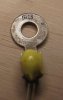
I was unable to recognize the markings on the ring. I have attached an image of the part. Let me know if you recognize it.
 

Attachments

  • IMG_1644.jpg
    IMG_1644.jpg
    49.7 KB · Views: 45
David, I checked the good part with a VOM diode tester, and its shows a 0.0V drop in both direction. There doesn't appear to be diodes in this thermistor.

Thanks,
Ben
 
Typically, the 'thermistors' were a stack of diode junctions in one package. The key is how many 0.6 volt drops are involved as the number of junctions varied.

I think some of those dang Sonys did use real thermistors. I suppose the designer was trying to manage bias drift by goosing up thermal compensation beyond what's possible with silicon junctions. In any case, the schematic would be MOST helpful.
 
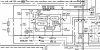
Mike, I attached the relevant portion of the schematic. It appears once either of the thermistors goes up in value, the chip begins to sink some current and opens the amplifier outputs.
 

Attachments

  • thermistor.jpg
    thermistor.jpg
    82 KB · Views: 34
The devices are PTC (positive temperature coefficient) thermistors. Their resistance rises as temperature rises, and Sony is using them to detect heatsink overtemp, which will disconnect the load once a specific temp is reached (60°~70°C is typical). Unlike an NTC (negative temperature coefficient) thermistor, the resistance of the PTC device rises fairly slowly until the temperature hits what is called the 'knee' or the 'Curie point', and then the resistance goes up to a very high value very quickly. Because they are not used in a low resistance mode, their room temperature resistance is not important.

In any event, Newark carries a few Murata devices that will work fine. I've found one here with a Curie point of 60°C, which should be fine to replace the original device.

FYI, I strongly recommend replacing BOTH of the original devices so that the voltage drop on them is equal...more or less.
 
Gentlemen, I stand corrected!! Thanks,

David

The devices are PTC (positive temperature coefficient) thermistors. Their resistance rises as temperature rises, and Sony is using them to detect heatsink overtemp, which will disconnect the load once a specific temp is reached (60°~70°C is typical). Unlike an NTC (negative temperature coefficient) thermistor, the resistance of the PTC device rises fairly slowly until the temperature hits what is called the 'knee' or the 'Curie point', and then the resistance goes up to a very high value very quickly. Because they are not used in a low resistance mode, their room temperature resistance is not important.

In any event, Newark carries a few Murata devices that will work fine. I've found one here with a Curie point of 60°C, which should be fine to replace the original device.

FYI, I strongly recommend replacing BOTH of the original devices so that the voltage drop on them is equal...more or less.
 
Back
Top Bottom