


MattiaM
Active Member
I recently refurbished a Sony TA-5650 v-fet, with a full recap, replacement of the killer diodes, addition of the voltage doubler on the power supply and replacement of the speaker relay. Bias adjusted fine at 50mV and the DC offset at the speaker output is about 2-3mv on one channel, and 15mV on the other. Not as low, but still fine, so I did not change the transitors in the differential pair.
Now, it works great but there is a very annoying loud pop when I switch it off. There are a lot of threads on this, and many say these are old amps so it will happen, and all the Sony 5650 and 4650 I have seen do pop when switched off. In my (very limited) experience, in most cases cleaning the on-off switch would reduce the problem significantly. However, for the amplifier I currently have on the bench this is not the case, and I want once and for all to be able to find and troubleshoot where the noise comes from.
What confuses me is that there is a circuit that has been specifically designed to avoid pops when switching the amplifier on or off, but it does not seem to do its job.
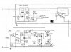
I attached the schematics (from the TA-4650, but components and values are exactly the same for the 5650). When the amplifier is switched off, the -highly negative -- rail raises towards 0, the base of Q406 becomes more positive (I guess through the discharge of C418?) than the emitter switching Q406 on, which shorts the B-E junction of Q404, turning off Q405 thus opening the relay (taken from the circuit description). The 'highly negative' rail is the -82V half way-rectified rail in the 5650; the less negative rail is the full wave-rectified -44V rail.
If the muting doesn't occur, I assume Q406 never turns on. Why?
I really have no idea how to systematically troubleshoot this as it all happens in milliseconds.
Any help would be greatly appreciated!
Now, it works great but there is a very annoying loud pop when I switch it off. There are a lot of threads on this, and many say these are old amps so it will happen, and all the Sony 5650 and 4650 I have seen do pop when switched off. In my (very limited) experience, in most cases cleaning the on-off switch would reduce the problem significantly. However, for the amplifier I currently have on the bench this is not the case, and I want once and for all to be able to find and troubleshoot where the noise comes from.
What confuses me is that there is a circuit that has been specifically designed to avoid pops when switching the amplifier on or off, but it does not seem to do its job.
I attached the schematics (from the TA-4650, but components and values are exactly the same for the 5650). When the amplifier is switched off, the -highly negative -- rail raises towards 0, the base of Q406 becomes more positive (I guess through the discharge of C418?) than the emitter switching Q406 on, which shorts the B-E junction of Q404, turning off Q405 thus opening the relay (taken from the circuit description). The 'highly negative' rail is the -82V half way-rectified rail in the 5650; the less negative rail is the full wave-rectified -44V rail.
If the muting doesn't occur, I assume Q406 never turns on. Why?
I really have no idea how to systematically troubleshoot this as it all happens in milliseconds.
Any help would be greatly appreciated!
Last edited:


