• The move to the new server is done. There are some software and database maintenance updates in process. This has us passing the hat around to help out. We appreciate any donations. Seriously, even a dollar helps. The payment page may be found here - https://www.audiokarma.org/support.html

Sony ta-n80 channel blown, cause?

TrevorBarten

Well-Known Member
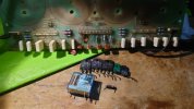
I made a post a few hours ago about getting the bias correct on my ta-n80 amplifier. I ended up setting the bias after the amp had fully warmed up and everything seemed fine, it kept the bias well and didn't do anything weird. So after this I turn it off, go to test it and get no sound. I tried a few things but nothing worked so I pulled the left channel input and put that into the fixed left input while the right channel was still in the variable input I also disconnected either just the left channel, or both I do not remember 100% from the pre amp while still keeping them connected to the power amp to see if tapping the connectors would produce anything. Before I could even try tapping the connector the amp almost immediately started smoking and shot into protection. After this I pulled it out with a heavy heart and started disassembling to see what went wrong. I found out that the driver transistors for the left channel, three of the six output transistors for the left channel, one of the 10 ohm emitter resistors, a zero ohm resistor and the left speaker relay had all gone. While very annoying especially after just spending a bit of money on this amp this is all fairly easy to replace even if the transistors might not be cheap. However I am making this post mainly to ask why this happened. Is the screwing around with the inputs the reason for this? I do not really understand why this would be an issue but admittedly I do not have a ton of experience with a/b power amps. I had it running on idle for atleast an hour to adjust the bias and it showed no signs of issues. I did redo the solder joints for the transistors but I checked for shorts or otherwise unwanted bridges and found nothing. And the 1 hour plus idle session was after this. While I had no sound during testing I also am not familiar with the setup and it is very possible I just connected something incorrectly. Since the dc offset adjustment was working I doubt that there was a relay that wasn't engaging or otherwise something obstructing the signal. I checked the manual on instructions that might caution the user to not use it in the way I did but I did not find anything like this either. Ofcourse that doesn't have to mean much but if there was such a confirmation I would feel much more at ease with repairing the amp by just replacing these components.9f7414da-836e-471e-8625-6104662c5ae8.jpeg
 
Last edited:
Register to hide this ad
After some more searching and reading I figured out that the d312 diode is also gone. I have read that it is unobtanium but I am sure that some modern replacement will work.... The same diode on d311 is not shorted but it gives some unexpected readings (1.7 voltage drop one way, 0.3 the other) so I think I probably will have to replace both.
 
Tomorrow I will check all the other fusible resistors for shorts. For now I am planning to order:

Q404 2SA1306A-0 (toshiba) -> MJE15033G (onsemi)
Q403 2SC3998B-Y (toshiba) -> MJA15032G (onsemi)

both C3423 transistors read ok with a multi meter so I do not believe they need to be replaced.

C3856 (sanken) -> 2SC3856 (sanken) if chip one stop allows me to order there, otherwise 2SC5200N (toshiba) (non obsolete version of a transistor successfully used on a diyaudio thread from years ago). I can also order these from digikey but they do not have the A1492.
A1492 (sanken) -> 2SA1492 (sanken) same story with chip one stop, otherwise I will probably opt for the 2SA1943N (toshiba)

As for the known bad resistor I will just order whatever is available locally that has the correct specs of 1/2 watts and being fusible. I am not sure yet if that is all that needs to be replaced. Input on this regarding the cause of the problem would be really helpful.

As for the relays I was thinking of just ordering the set sold on ebay for 12 euros, but it is not a priority. I think the old one might still work even if the plastc got very hot, even if it is just to test.

I would also really appreciate some input on the HZ3ALL diodes. In the aforementioned diyaudio thread the suggested replacement was the Bzx55c2v7 which has some different specifications like a lower impedance rating and a higher max power dissipation. I do not know what should be prioritised in this instance in terms of specs but the Bzx55c2v7 has since also gone out of production so it is not an option.

Also mentioned in the diy audio thread was the UPA68HA UPA68 Dual N-Channel JFET being faulty. I checked it for shorts on my board and there weren't any but I do not know if that is enough to know if it actually ok or not.

As for the actual reason this happened, I am still not sure. When the left channel blew up I could hear sound through the left speaker so the speaker cables atleast on the left channel where connected. I am not sure if sound being produced in this situation means that there is no short or not.
 
Also what would be the best approach for using a dim bulb tester? I built a very primitive one for a previous project but this being an A/B amp I doubt that the 50 watt bulb will even allow the capacitors to charge quick enough? Or will it just stay in protection for longer than without the dim bulb tester? When I turned on this amp before it died it drew quite a bit of current as the lights in my workplace dimmed for split second, that in itself is not uncommon but the amount is probably the most I have seen yet...
 
For now I have decided to go ahead and order:

15032g 3x
15033g 3x

2sc5200 10x
2sa1943 10x

bzx55c2v7 10x (a different variant was still in stock luckily)

10hm 1/2 watt 5% fusible 10x

I decided to order a bunch of spares should something go wrong again so I can both keep testing if one attempt does fail and I had to order more than 50 euros in value anyway to avoid shipping costs, so the extra spares are essentially free anyhow. I will order the relays on ebay as I do not know much about relays and the service manual just says relay under the part description.
 
I have now tested every resistor on main board a, b and the protection circuit. I have found quite a few broken ones as well as some more broken transitors.
Pictured now are all the broken parts, excluding some resistors maybe, that I have found. I have also written them down. I hope I can find some replacements for the transistors...
DSC_1546.JPG
 
Back
Top Bottom