


Racingh11
Super Member
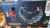
I needed a battery charger for a 144V hybrid tractor project I'm working on. I also have a MTX Soundcraftsmen S800 amp for parts. It is the same style as the old Soundcraftsmen PCR800, PM840/860 with regulated power supply. I needed the amp section to repair an S860, so I had everything else left over.
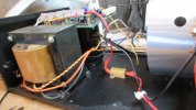
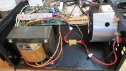
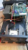
I added a 25W 0.1 ohm resistor in the current sense circuit where R31 0.27 ohm was. I mounted it to the chassis. Added a 1k ohm resistor in series with the current sense pin. I also added a 500 ohm pot. in parallel with the 1.3k ohm current sense resistor. These mods allow me to adjust the current limit. The power supply will lower the supply voltage when the circuit is activated.
For voltage I need about 158-160V, so I replaced R11,19 33k ohm resistors with 39k ohm. This allows the voltage pot. to adjust from about 148-180V no load voltage, up from stock 140V. Also replaced the stock 75V power caps with 100V to handle the voltage increase. And separated the transformer secondary center tap from the chassis ground to float the output.
*FYI, the part numbers are for the old schematic, not what's on the MTX boards.
It also has the stock adjustable temp sensor in the transformer. I left it alone for now and need to do further long term testing. My dummy loads get hot real quick. It blows the stock fuse when I run 10A steady, and the transformer also gets warm. I turned it down to 5A for now.
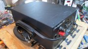
I also added a handle.
More testing will be done soon on actual batteries and temps will be monitored and performance adjusted.
I designed the speed controller for the tractor too. It is a speed governor circuit with current control and several safety features, and an external ammeter display. Those were from scratch and not from existing products. It's working good so far, just doing the fine tuning now.
I added a 25W 0.1 ohm resistor in the current sense circuit where R31 0.27 ohm was. I mounted it to the chassis. Added a 1k ohm resistor in series with the current sense pin. I also added a 500 ohm pot. in parallel with the 1.3k ohm current sense resistor. These mods allow me to adjust the current limit. The power supply will lower the supply voltage when the circuit is activated.
For voltage I need about 158-160V, so I replaced R11,19 33k ohm resistors with 39k ohm. This allows the voltage pot. to adjust from about 148-180V no load voltage, up from stock 140V. Also replaced the stock 75V power caps with 100V to handle the voltage increase. And separated the transformer secondary center tap from the chassis ground to float the output.
*FYI, the part numbers are for the old schematic, not what's on the MTX boards.
It also has the stock adjustable temp sensor in the transformer. I left it alone for now and need to do further long term testing. My dummy loads get hot real quick. It blows the stock fuse when I run 10A steady, and the transformer also gets warm. I turned it down to 5A for now.
I also added a handle.
More testing will be done soon on actual batteries and temps will be monitored and performance adjusted.
I designed the speed controller for the tractor too. It is a speed governor circuit with current control and several safety features, and an external ammeter display. Those were from scratch and not from existing products. It's working good so far, just doing the fine tuning now.
Attachments
-
 IMG_1903.JPG92.1 KB · Views: 8
 -
 IMG_1902.JPG65.1 KB · Views: 7
 -
 IMG_1901.JPG82.3 KB · Views: 7
 -
 IMG_1900.JPG67.6 KB · Views: 10
 -
 IMG_1898.JPG109.9 KB · Views: 10
 -
 IMG_1897.JPG108.2 KB · Views: 10
 -
 IMG_1896.JPG79.7 KB · Views: 8
 -
 IMG_1895.JPG103.1 KB · Views: 8
 -
 IMG_1894.JPG93 KB · Views: 8
 -
 IMG_1893.JPG87.8 KB · Views: 8
Last edited: