• The move to the new server is done. There are some software and database maintenance updates in process. This has us passing the hat around to help out. We appreciate any donations. Seriously, even a dollar helps. The payment page may be found here - https://www.audiokarma.org/support.html

Soundcraftsmen PCR800 buzzing channel

The Rebel

Active Member
For the Soundcraftsmen techs in here. I have a nice PCR800 amp that has a fairly loud buzzing in one channel with the volume down, and not so loud in the other channel. It seems to be bleeding over into the other channel. It still has output from both channels and sounds great on small test speakers. I checked DC offset;
Left channel (buzzing channel) 147mV
Right channel 1.3mV
Voltage at PS caps;
Left channel 93V
Right channel -73V
So far I don't know exactly what to check in the PS board to find out where the high voltage is coming from. Any ideas where to start on this? Thanks
 
Register to hide this ad
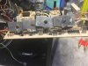
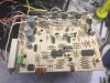
Trying to find out what to check on this control board. The PS filter caps did have different readings from one to the other. I had one with 93V across it, the other had -73V, which is spec. Where should I look on the PS board for problems?
 

Attachments

  • IMG_1796.JPG
    IMG_1796.JPG
    68.4 KB · Views: 72
  • IMG_1795.JPG
    IMG_1795.JPG
    75.4 KB · Views: 71
Update on the PCR800. I'v replaced all 4 SCRs, and all L01, and A93 transitors in the ps board and still getting the same high voltage on the positive rail. Is it possible that a PS cap would cause this issue?
 
Update on the PCR800. I'v replaced all 4 SCRs, and all L01, and A93 transitors in the ps board and still getting the same high voltage on the positive rail. Is it possible that a PS cap would cause this issue?
A cap could not cause that. The SCRs act as a bridge rectifier would in most amps. And they are fired to maintain +/-70V. So if you get more than that on one rail, then the SCRs are either shorted and letting transformer voltage through, or something is triggering them on to make it do that. And Q3,5 are the ones that fire the positive SCRs. If the negative rail works, then it's not the op-amp or phase sensing circuits.
 
Last edited:
Update on the PCR800. I'v replaced all 4 SCRs, and all L01, and A93 transitors in the ps board and still getting the same high voltage on the positive rail. Is it possible that a PS cap would cause this issue?
Looking at the schematic again and I see another possibility. It could be in the circuits related to the IC section U2D. It is the op-amp section that compares positive rail voltage and adjusts the PCR accordingly. R11,12,16 go to the IC input and compare to the same reference the neg side uses and appears to be working fine. Looks like it should be about 4.375V at pin 13 of that IC.
 
Actually, I don't think it's that either, since it charges both on every half cycle. It really has to be something with those control circuits and SCRs. The op-amp goes negative on every half cycle or 120hz and that pulls both Q3 and Q4 on to turn on Q5 and Q6 to fire the SCRs. Should check the resistors in those areas too.
 
Ok, I'll check voltages on the IC. There are no pinouts for the ICs on the schematic so I will number them 1-7 on top pins, and 8-14 on the bottom pins.
Left and right in the pic. The left rail is the positive rail. The positive rail voltage with Variac at 100% is 103V now. negative rail is -76V.
The white rectangular resistor to the left is getting hot, and the fan speed is ramped up.
 

Attachments

  • IMG_1879.JPG
    IMG_1879.JPG
    124.1 KB · Views: 61
  • IMG_1880.JPG
    IMG_1880.JPG
    75.5 KB · Views: 56
  • IMG_1796.JPG
    IMG_1796.JPG
    106.2 KB · Views: 56
Here is the data sheet and pin ID for the 4136 op-amp.

At first glance I can tell you; your temp sensor voltages are right on.
Pins 1, 8, 14 on the U1 IC, (which is LEFT 1, 7, 8 on your list). are from temp comparison regulator voltage. Adjusted by potentiometer
Pins 11 and 7, (LEFT 4 and 14 on your list) are pos and neg 15V supply.
Pins 3, 10, 12 (LEFT 10, 3, 5 on your list) are temp sensing circuit outputs from the IC. they go negative when temp is hot.
Pins 2, 9, 13 are temp sensor inputs relative to the IC (LEFT 2, 6, 9 on your list) All normal so far.
Pins 4, 5, 6 (LEFT 11, 12, 13) are for the two speed flashing power light. Two stage astable multi-vibrator

Pins 7 and 11 on IC U2(RIGHT 14, 4 on your list) are neg and pos voltage.
Pin 1(RIGHT 8 on your list) is fan control input. This goes low/negative to turn fan on when hot.
Pin 2(RIGHT 9 on your list) is comparison voltage for fan control. It is normal.
Pin 3(RIGHT 10 on your list) is fan output voltage. It goes high to turn fan on.
Pin 4(RIGHT 11) is PCR control output voltage to the SCR control transistors. It pulls low/negative to turn on SCRs
Pin 5(RIGHT 12) is PCR voltage control from rail voltage comparator op amps. It goes negative to increase phase/amperage through SCRs.
Pin 6(RIGHT 13) is phase timing circuit voltage. It charges every half AC cycle from the transformer.
Pin 8((RIGHT 1) is negative sensing rail voltage
Pin 9(RIGHT 2) is ground
Pin 10(RIGHT 3) is negative rail control voltage to Pin 5
Pin 12(RIGHT 5) is positive rail control voltage to Pin 5
Pin 13(RIGHT 6) is positive sensing rail voltage
Pin 14(RIGHT 7) is regulated comparison voltage. Adjusted by potentiometer

You might have an open ground for pin 9 of IC U2. Also pin 14 should be slightly higher than pin 8. You could have an open R10 or board trace. Pin 13 should probably be around 4 or 5 volts and seems to be open as well. Also the positive output is lower on pin 12, than neg on pin 10. This means the positive side is commanding the PCR on further than neg rail. And it's inputs at pins at 13 and 14 seem to be open or dead. I'm still not sure how this could make only one rail regulate properly as this would likely effect both pos and neg. As both pos and neg SRCs are fired at the same time by the same source coming from U2 pin 4. It seems you might have a couple of problems. check the bottom of the board for damage or bad solder joints on the IC sockets. Check the resistors.

If you redraw your pins and voltages, I can edit this and get rid of all the double pin numbers as it makes this confusing.

 

Attachments

Last edited:
Also you can put your scope leads on the brown and yellow wires coming from the transformer to the power board. It will show a notch in the 60 hz sine wave where the SCRs are triggered and passing current. The notch will grow as the amp load increases.
 
Ok, this helps. I wish I would have thought about the data sheet for the 4136, I've got to get my head in the game and keep it here. Thanks for posting that. Looks like I will be searching for bad resistors. Wait, this amp has a two stage multi-vibrator? Huh? Glad wife isn't working on it. :D I know, I know, stop with the crass jokes. It's late.
 
Also you can put your scope leads on the brown and yellow wires coming from the transformer to the power board. It will show a notch in the 60 hz sine wave where the SCRs are triggered and passing current. The notch will grow as the amp load increases.
My scope didn't work out. Looks like I will be looking for a different one soon.
 
The weird thing is those voltages would be correct if pins 13&14 and 8&9 were switched or if the schematic was numbered wrong. It really does seem that way. You could see which one has low resistance to ground. Pin 9 like the schematic says or pin 13 like it seems to be. On the RIGHT IC.
 
Did you write them down in reverse order on that row you have labeled RIGHT 1-7 ? Because that would explain it.
 
Did you write them down in reverse order on that row you have labeled RIGHT 1-7 ? Because that would explain it.
Not that I am aware of. It should be just like the one on the left. I am going to try to make a copy of the pin out diagram and go back through all the voltage checks.
Then I am going to open my working 800 and do the same with it and write all the voltages down to compare them. That may help me wrap my head around it easier.
I have gotten spoiled by the labeled PCBs on most of my other gear, this one takes a little longer for me to trace down each resistor in the circuit I'm working on. Your help has been a Godsend on learning these amps. I really appreciate it.
I know exactly what you mean about having to trace through these to find what things are. I was already thinking I am going to write down all these voltages on the next one I do so I have a reference from now on. I learn something every time I go through these schematics and think about how they work. That's part of why I like answering questions.
 
I'll try to get these off my good 800 and post them up in here. I also have a good running PM860, I can check those too and see how they match up.
 
I like theses amps and have several. I had one a while back that I chased a problem in for quite some time before finally discovering it was a broken trace that was not visible to the naked eye. Only found it by deductive reasoning and a meter. Check voltages everywhere when in question.
Good Luck
 
I like theses amps and have several. I had one a while back that I chased a problem in for quite some time before finally discovering it was a broken trace that was not visible to the naked eye. Only found it by deductive reasoning and a meter. Check voltages everywhere when in question.
Good Luck
Do you remember what the problem you were chasing was? Broken trace in the PS board , or amp board? Thanks for posting.
 
I had one that was a unit for an audio rental company. The transformer came a bit loose and it rubbed on the edge of the board and through a trace. That one lost charging on every other phase and blew the fuse when loaded because it had to charge twice as fast and half as often.
 
Back
Top Bottom