You are using an out of date browser. It may not display this or other websites correctly.
You should upgrade or use an alternative browser.
You should upgrade or use an alternative browser.
sparkos on Marantz 2325
- Thread starter ducati2
- Start date


Swapped boards tonight and things are starting to make sense! First thing I found was a jacked up molex connector, where one of the wires was backing out and not making connection! Bingo! Huge find. Then after a drop of super glue to keep that wire in the molex, I swapped boards, and set the dc offset on both boards... no problem. The bias set great on the right side (formerly on the left), but the bias on the left channel (formerly right), still was way too sensitive to set. THEREFORE, it appears at this time all I need is a replacement bias pot. The 25 turn Bourns should be here for the weekend. This hobby can really test a guy! But it is great to know there are people out there to keep us plugging away, probing and pondering until things start to work out!
I may still need help before this is over, but THANK YOU sanjib for all your help thus far!
I may still need help before this is over, but THANK YOU sanjib for all your help thus far!
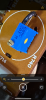
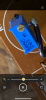
Embarrassing, but I can’t figure how to install the bournes 25 turn ... I used the center lead to where the original pot case went, then 2 outer leads for the other 2 holes, but pot is not responsive at all. Maybe need to reassign leads, but not sure how.I hope the new trimmer will fix it otherwise we may need to dig deeper!
I did extend length of trimmer middle wire thinking it needed to go to the hole where the OEM trimmer body was. I will remove and swap wires around, but it seems one would need to be extended as the bournes leads are only about 5/16” long.Now I can't remember how was the original trimmer was installed. But, I never used any wire ( I think you used an external black wire) to short the two pins. I will suggest inserting the pins in holes and solder at the solder side of the board.
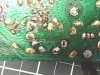
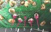
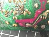
looking at the back side of the board, there appear to be only 2 veins to connect to. While the oem pot only used holes number 1,2,4 and 5,, the hole I marked #3 was unused and there is no solder point for that hole. I have also shaded one vein red and the other yellow. Bournes has 3 legs and this photo shows how I currently have it soldered into place, but it is coming back out since that configuration does not work either. With only 2 veins in the pcb that seem to involve the pot, it seems if I put the middle leg in a hole on one of the veins and then either one of the outer legs of the bournes in the other vein, it should work. Agree? FYI- holes 1 and 5 are where the oem pot outer body was held in place.