• The move to the new server is done. There are some software and database maintenance updates in process. This has us passing the hat around to help out. We appreciate any donations. Seriously, even a dollar helps. The payment page may be found here - https://www.audiokarma.org/support.html

Speakerlab 7 Crossover conundrum

jupitersspot

Active Member
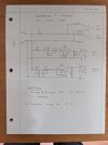
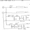
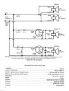
I have a set of new-to-me Speakerlab 7 speakers. The cabinets are rough and need some work, and I want renew the electronics in the crossovers. I have found online a schematic for the crossover network in the speaker (link to that AK post), but after disassembling my speakers I find that my speakers have a slightly different crossover, with additional resistors in the branches driving the mid and tweeter horns. To make matters worse, two of the resistors are labeled using very faded color bands that I can no longer decipher (maybe you can?).

Three images attached below:
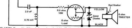
1) Crossover diagram I found on the internet (not sure of vintage or version, since apparently there were 3 or 4 crossovers in use on the sevens)
2) Diagram I drew illustrating what I found in my speaker (note I do not know values for inductors A,B,C, or resistors R1 and R2)
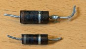
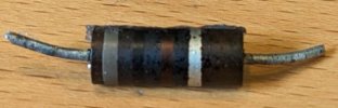
3) The two resistors I pulled out of my speaker (R1 and R2 from my diagram)

I have pulled R1 and R2 from both speakers and measured their value out of the circuit with my meter:
SpeakerR1 Value (thinner, lower one in my image)R2 Value (fatter one, on top in my image)
SN 11193720 Ohms33 Ohms
SN 11193845 Ohms25 Ohms

So I am faced with a challenge: how can I determine the values of the faded-label resistors, or should I change my crossover network to match the one I found on the internet (which clearly has different capacitor and resistor values)?

[edited to make clearer the measured values of R1 and R2]
 

Attachments
  • Crossover from internet.jpeg
    Crossover from internet.jpeg
    90.6 KB · Views: 52
  • my speaker.jpg
    my speaker.jpg
    67.8 KB · Views: 51
  • R1 and R2.jpg
    R1 and R2.jpg
    87.7 KB · Views: 45
Last edited:
Register to hide this ad
Start by measuring the existing ones with an ohmmeter. They get pretty light duty is a speaker crossover and are unlikely to have drifter too much.

Those don’t look like 10 watt or 20 watt resistors, they look to small. Is that just my brain misinterpreting their size?

BTW, to me they look Brown-Black-Black-silver (10 ohm, 10%) and Gray-Black-Brown-Silver (800 ohm, 10%). If they measure close to that you have your answer.

I’d keep it original if it seems to have come from the factory that way.
 
Last edited:
Start by measuring the existing ones with an ohmmeter. They get pretty light duty is a speaker crossover and are unlikely to have drifter too much.

Those don’t look like 5 watt or 10 watt resistors, they look to small. Is that just my brain misinterpreting their size?
I edited my post, which wasn't clear, but the values in the table are the values I measured with an ohmmeter. They differ, a lot.
To my untrained eye, the smaller resistor seems to be a 2 watt, and the larger one could be a 5 watt.
 
HA! I also exited my post. I now get your point about wanting to go back to the schematic version.

Do those carbon resistors seem like a repair?

BTW, I had a pair of Speakerlab 3 and 7s back in the day. Pretty great sounding. Post images of your progress, or at least when you are done.
 
Do those carbon resistors seem like a repair?
I really don't know. Clearly someone has opened these up before; the paint on the back of both horns had been scraped off by the last tinkerer before I got there. But I doubt these carbon resistors are a hacked-together addition, and if they're replacements I suspect they are accurate replacements for what had been there originally. But I'm just guessing.
 
There is only one added resistor in your drawing ss your R1 exists in the factory drawing as an 8 Ohm, 10 Watts resistor. Your R1 appears to be BRN-BLK-BLK = 10 Ohm as noted by @Semanon.

Your R2 is positioned across the combined load (R1, Lpad, tweeter). I think that one is GRY-BLK-BLK = 80 Ohms. Such a value might be used to tame the load impedance peak (and hence also audio response peak) that occurs at the tweeter mechanical resonance frequency but I don't know if that's why it has been used here.
 
Could that third band of your R1 be a cooked gold band?

Resistor R2.JPG
That would make it x 0.1 for 8.0Ω, which would be consistent with the schematic.

Tweeter Filter.JPG
 
Perhaps someone did a little freelance crossover design and could not find the correct wattage resistors. They made due with what they could find (no Digikey in the 70s). So they ended up with too-small resistors and they cooked over time.

Based on this little fable, I’d go back to the original Speakerlab design, or at least the original power ratings for the power resistors.
 
Last edited:
You should check with these guys on Facebook. They know all things Speakerlab.
This is the second time you've given me this advice, and again it's golden advice.

Here's what I learned:
You have an earlier version than that diagram reflects [referring to my image "Crossover from Internet" in original post], I have attached the schematic for your particular version.
Later versions changed the crossover points and slopes to accommodate different mid drivers and increase power handling, but it is always best to use original parts for a particular build or version.
Attached diagram shows intended circuit. Spoiler, my R1 is 8 Ohms, and R2 is 16 Ohms (5 Watt).
 

Attachments

  • Old Old Old X7.jpg
    Old Old Old X7.jpg
    78.7 KB · Views: 20
The resistor additions and the L and C value changes have more to do with accomodating different driver impedances (4, 8, 16 Ohm) and sensitivities (dB/Watt) than it does changing crossover frequencies or "slopes". The low/mid crossover freq does change somewhat from year to year but the mid/high crossover freq remains at 5kHz throughout.

The suggestion that there are changes in "slopes" (there are not) indicates your FB informant doesn't understand linear filters.

I suggest again that you spend some time reading the (excellent) Speakerlab documentation from when these speakers were made and sold.
 
Last edited:
Back
Top Bottom