• The move to the new server is done. There are some software and database maintenance updates in process. This has us passing the hat around to help out. We appreciate any donations. Seriously, even a dollar helps. The payment page may be found here - https://www.audiokarma.org/support.html

SPEC 1 Frequency Response Guidance Required

I would focus your attention on the buffer amplifier. Clearly it doesn't like its front end being dragged close to ground (low volume setting) and that is affecting its HF response. You definitely replaced the two 3.3uF non polarized caps in each line buffer amp with the right value when you recapped?

I was concerned about that so I disconnected the wire that connects the output of the volume control to pin 1 on AWG-035. I connected the probe to that wire and saw the exact same result. From what I'm seeing, it's the volume control itself.

That gives me an idea: disconnect the input and output of the volume control, feed the signal in one side and probe the other side to see if I see that roll off... Maybe tomorrow night...

And, yes, the entire preamp was recapped.
 
Absolutely I do and the OP does too. That has been covered in the early posts in this thread.

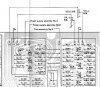
The BLOCK diagram and the SCHEMATIC are at odds. The block diagram has a track pin on the pot going to the buffer (line out) stage directly.
The schematic has the WIPER going to the buffer (line out) stage. They are wired differently and one configuration would quite possibly cause the HF falloff. I want to know which way it is actually wired.

I've had a few SPEC1s and disposed of them because their response was nothing like their specs would have you believe. I never bothered to investigate because I simply onsold them to collectors.

Check the wiring to the attenuator is the same as this:

attachment.php


You do know the volume control has two sections per channel?

more info:
http://www.audiokarma.org/forums/showthread.php?t=314900
 

Attachments

  • wiring 082.JPG
    wiring 082.JPG
    110.2 KB · Views: 62
Last edited:
I can put my hands on a Spec1 in a few weeks so I'll test it and report back. It may be inherent in all Spec1s. If the filter stage has a low impedance output and sees a reasonably constant load/impedance, its HF response should stay pretty much the same, regardless of the volume setting.
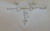
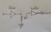
I always thought the SEPP buffer had a high input impedance so it suggests to me the volume pot is wired incorrectly, has some parasitic capacitance on the internal substrates or the filter stage has a way higher output impedance than it should at HF frequencies and is being affected by the buffer stage somehow.
My interpretation of the block vs schematic is as follows:
attachment.php

attachment.php


I don't think Pioneer would muck it up, but crazier things have happened.
 

Attachments

  • block.jpg
    block.jpg
    40.5 KB · Views: 61
  • schem.jpg
    schem.jpg
    56.1 KB · Views: 61
i have an idea,
do a test using only one section of the volume pot vr1 operational at a time. start with the one connected to the input attn sw4 first.
referring to the block diagram, on the input section, short the wiper to the clockwise terminal, to offer no attenuation. you only need to do it on one channel, if both channels behave the same! (do both channels behave the same in your previous freq resp tests?)
do the same freq response tests as previously, with the shorted input vol section.
Now undue the input vol section short and do the same shorting op but for the output section this time
measure again, interested to see the differences with attenuation.
another interesting test to try is the freq response with change in the balance control settings
good luck rick
 
Last edited:
little more thought, be careful, by rights the ground terminal of the volume pot should be lifted, or the pot section isolated, you do not want to short the input buffer or filter o/p to ground, if the wiper is set for minimum. I do not think a load of less than 1k is a good thing to do.
 
XL, I'll be putting the Spec on the bench about 10:00 AM Sat morn. Looks like you guys may be on to something....
 
XL, I'll be putting the Spec on the bench about 10:00 AM Sat morn. Looks like you guys may be on to something....

Thanks Lee.

Been a busy few days and the weekend looks to be the same so I haven't had a chance to get back at it. Besides, I kind of want to see your results before I rip my baby apart further. I will be checking in here periodically though.

If I'm right, you will only see the frequency response to spec at max volume. Anything less than that will show a logarithmic trail off starting at about 20kHz.

My suspicion right now is that it has to do with the volume control itself...
 
Self-Test.... Can't seem to upload...back in a bit...


Anyone else having problems uploading attachments?
 
Last edited:
Thanks Lee.

Been a busy few days and the weekend looks to be the same so I haven't had a chance to get back at it. Besides, I kind of want to see your results before I rip my baby apart further. I will be checking in here periodically though.

If I'm right, you will only see the frequency response to spec at max volume. Anything less than that will show a logarithmic trail off starting at about 20kHz.

My suspicion right now is that it has to do with the volume control itself...


You are absolutely correct. Meets spec at output voltage of 1.874.

Another interesting measurement.....at 463 mv output phase lag/lead is wayyyyy different that at 1.874 volts output....
 
You are absolutely correct. Meets spec at output voltage of 1.874.

Another interesting measurement.....at 463 mv output phase lag/lead is wayyyyy different that at 1.874 volts output....

Awesome to have the confirmation. THANKS!!!.

Isn't it curious that it's so different as soon as you turn down the volume control?
 
Yes, I'd like a copy of the file please, email sent

Thank You is for for running the test.

Now we KNOW, and can start LOOKING for why....
 
Back
Top Bottom