• The move to the new server is done. There are some software and database maintenance updates in process. This has us passing the hat around to help out. We appreciate any donations. Seriously, even a dollar helps. The payment page may be found here - https://www.audiokarma.org/support.html

Spec-2 Troubleshooting Output Transistors

dwood357

New Member
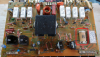
Looking for advice on determining if the output transistors are leading to a channel appearing to be out.

What I've determined is that I have the correct voltage at 15,16,21,22, but do not see any voltage at the output legs of the transistors.

I have taken each output transistor out and did a preliminary multimeter test, and they did not seem to show issues, but I am now worried that my test method is not adequate.

https://vetco.net/blog/test-a-transistor-with-a-multimeter/2017-05-04-12-25-37-07

I have also replaced Q2-Q13, so far.

My question then is, on the Spec-2 are there certain places/things to probe that would be telling of where the problem would be stemming from.

Thank you in advance!
 
Register to hide this ad
Welcome to AK...

We want to help, but are hamstrung by:

You have NOT detailed what you have decided is the problem.
You have not communicated the action or INaction of the protect relay.
You have not detailed your replacement transistor choices for Q2 thru Q13.
You state pins 15,16, 21 & 22 as being correct, without posting WHAT the voltages ARE.
We don't even know the cleaning status of the unit, i.e. 20 yrs untouched or freshly done.

On top of that, What's YOUR technical level? Don't want to insult, nor go over your head. Past history here isn't very enlightening.


My question then is, on the Spec-2 are there certain places/things to probe that would be telling of where the problem would be stemming from.
Yes: what were / are the ground referenced voltages on pins 14 & 23. The base drive voltages.


As for testing individual transistors , read this, use form on post 11 to report readings on each and every output transistor.
https://audiokarma.org/forums/index.php?threads/bipolar-junction-transistor-testing-basics.43186/
 
Welcome to AK...

We want to help, but are hamstrung by:

You have NOT detailed what you have decided is the problem.
You have not communicated the action or INaction of the protect relay.
You have not detailed your replacement transistor choices for Q2 thru Q13.
You state pins 15,16, 21 & 22 as being correct, without posting WHAT the voltages ARE.
We don't even know the cleaning status of the unit, i.e. 20 yrs untouched or freshly done.

On top of that, What's YOUR technical level? Don't want to insult, nor go over your head. Past history here isn't very enlightening.


Yes: what were / are the ground referenced voltages on pins 14 & 23. The base drive voltages.


As for testing individual transistors , read this, use form on post 11 to report readings on each and every output transistor.
https://audiokarma.org/forums/index.php?threads/bipolar-junction-transistor-testing-basics.43186/

Thank you for the reply, I can elaborate.

As far as my experience, I am a software engineer and have done some hardware work in the past both analog and digital and have done some general repairs to amps, you can get technical and it should not go over my head, what I feel I am missing is the general approach to diagnosing problems like "channel being out".

The history on this unit is somewhat unknown, it appears at some point someone has opened it up and soldered some of the wire wrap points, the components appear to be original. I do know that it has been running in someones system for the past 7 years without being worked on.

I've determined that I am unsure on where the problem is, I do know that if I do a Left-Right swap, the channel outage follows the Left amp board.

The protection lamp does go off, and RL1 engages.

Measurements taken relative to Pin 18:

14 -> 0V
23 -> 0V

15 -> -90.8v
16 -> -90.8v
21 -> 90.8v
22 -> 90.6v

For the replacement parts, I was going off of another thread talking about restoration:

Q1 – 2SA798
Q2 - 2SA872 - 512-KSA992FBU
Q3 - 2SA872 - 512-KSA992FBU
Q4 – 2SD610A - MJE15032G
Q5 - 2SD610A - MJE15032G
Q6 - 2SD610A - MJE15032G
Q7 - 2SB630A = MJE15033G
Q8 - 2SA733 - 512-KSA733CLTA
Q9 2SC945 - 512-KSC945CLTA
Q10 - 2SC945 - 512-KSC945CLTA
Q11 - 2SA733 - 512-KSA733CLTA
Q12 - 2SD610A - MJE15032G
Q13 - 2SB630A = MJE15033G

Appreciate the help!
 
Saying RL1 engaging opens a can of worms, the service manual is rather inconsistent in naming them, the main schematic and the individual board schematics reuse labels.

The service manual main schematic calls out these:
RL1 primary surge current control relay
RL2 secondary surge current control and voltage selector relay
RL3 secondary surge current control and voltage selector relay
RL4 speaker disconnect relay <<< THIS is the protect relay.
RL5 muting relay
RL6 current limiter sensitivity control.

Transistor substitutions look fine.

The voltage measurements become more important the closer they get to 0v. Thus there is 0.689v and 0.003v.

There are several things I can read into 0.000v at pins 14 & 23.
but knowing the SPEC-2 something else rears it's head.
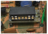
It is RL5 on the main schematic, also called RL1 on the power amplifier board schematic and parts location drawings.

upload_2023-2-22_20-19-35.png

It has been a source of trouble on them forever, and are recommended for replacement unconditionally.

It turns on the power output section of the amplifier. It fails, sticks open and closed and mysteriously for a reed relay, develops resistive connections.
read this thread, includes links for the part number from mouser.com:
https://audiokarma.org/forums/index...-relays-rl1-rl5-rl2-rl6.970170/#post-15044884
https://audiokarma.org/forums/index...output-on-left-channel.1012370/#post-16006534

upload_2023-2-22_20-5-29.png

Replace it. Can test by shorting across the contacts temporarily.
RL1 (RL5) is a spst (aka: 1 FORM A ) 24v reed relay ASR-017. It carries 26mA in the front end of the Spec-2 amp, doing a muting function.
https://www.mouser.com/ProductDetail/Littelfuse/HE751A2400?qs=X8LBAgEWIKJBfoi7amFn0Q==
 
Last edited:
Saying RL1 engaging opens a can of worms, the service manual is rather inconsistent in naming them, the main schematic and the individual board schematics reuse labels.

The service manual main schematic calls out these:
RL1 primary surge current control relay
RL2 secondary surge current control and voltage selector relay
RL3 secondary surge current control and voltage selector relay
RL4 speaker disconnect relay <<< THIS is the protect relay.
RL5 muting relay
RL6 current limiter sensitivity control.

Transistor substitutions look fine.

The voltage measurements become more important the closer they get to 0v. Thus there is 0.689v and 0.003v.

There are several things I can read into 0.000v at pins 14 & 23.
but knowing the SPEC-2 something else rears it's head.
It is RL5 on the main schematic, also called RL1 on the power amplifier board schematic and parts location drawings.

View attachment 2807825

It has been a source of trouble on them forever, and are recommended for replacement unconditionally.

It turns on the power output section of the amplifier. It fails, sticks open and closed and mysteriously for a reed relay, develops resistive connections.
read this thread, includes links for the part number from mouser.com:
https://audiokarma.org/forums/index...-relays-rl1-rl5-rl2-rl6.970170/#post-15044884
https://audiokarma.org/forums/index...output-on-left-channel.1012370/#post-16006534

View attachment 2807797

Replace it. Can test by shorting across the contacts temporarily.
RL1 (RL5) is a spst (aka: 1 FORM A ) 24v reed relay ASR-017. It carries 26mA in the front end of the Spec-2 amp, doing a muting function.
https://www.mouser.com/ProductDetail/Littelfuse/HE751A2400?qs=X8LBAgEWIKJBfoi7amFn0Q==


I am taking measurements with a fluke multimeter, and to clarify it was 0.000V at 14&23.

When the protection lamp goes off I see the relay R1 on the Power Supply Board.

As far as R1 on the amp board, I do have these on hand if it is a suitable replacement (found on another thread):

https://www.digikey.com/en/products/detail/littelfuse-inc/HE3351A2400/475790

If it is not I will get your recommended part.

Thank you!
 
Back
Top Bottom