• The move to the new server is done. There are some software and database maintenance updates in process. This has us passing the hat around to help out. We appreciate any donations. Seriously, even a dollar helps. The payment page may be found here - https://www.audiokarma.org/support.html

Spec sheet vs actual electrolytic capacitor discrepancy

Mai Tai

New Member
I’m in the process of replacing the electrolytic capacitors in a vintage 1947 Magnavox CR-197 radio/phono console, and ran into a small issue, where the voltage ratings on the can that I’m replacing don’t match the voltage ratings of the same cap on the radio’s original spec sheet. I’m trying to decide whether to go with what’s specified on the sheet, as I have capacitors of those values on hand, or if I should hold off and buy new capacitors to match what is actually lodged in the chassis.

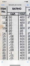
The cap in question is a typical aluminum can electrolytic type. The spec sheet indicates it should be a 10mfd/450v, 30mfd/450v unit, but what I’m seeing installed in the chassis is a 10mfd/475v, 30mfd/475v unit (see photos). The can does not appear to have been replaced at any point, so I’m assuming it’s original. I know that while MFD’s must be as close to original as possible, it’s generally ok to replace existing caps with ones rated with a higher V (never lower, though). With this in mind, I can’t rule out that they simply used one rated for 475v when they built the unit in 1947, because perhaps that was what they had available. On the other hand, I can’t rule out that someone simply made an error on the spec sheet, when specifying 450v.

In this case (and because I have plenty of room under the chassis), I’m simply replacing it with two individual capacitors, rather than a newer single can unit with both values. I have 10mfd/450v and 30mfd/450v capacitors on hand. Question is, do I just use them, as it’s what’s specified, or should I order 10mfd/475v and 30mfd/475v caps to match what’s actually in there? Anyone else ever run into this before?

Any advice is sincerely appreciated. Thanks.
 

Attachments

  • B6C03409-D263-413A-8C7A-96851B9CE3E5.jpeg
    B6C03409-D263-413A-8C7A-96851B9CE3E5.jpeg
    77.9 KB · Views: 7
  • F406CC06-D5EA-4957-BC1F-081705A46491.jpeg
    F406CC06-D5EA-4957-BC1F-081705A46491.jpeg
    36.7 KB · Views: 7
Register to hide this ad
As you mentioned, no harm in going with a higher voltage rating. Depending on cost and available space, I'd even look at using 500v or higher caps Generally, elytics are so much smaller these days you'll probably still have plenty of room...
 
If the part in the radio appears original, go with whats in the unit. That EIA code tells me week 43 in 1948,58, or possibly 68.

but given the choice of 450 on the schematic and 475 in the unit, I'd be fine using a 500v part to replace it. Worst case, power it and confirm what the voltage peaks at doesn't exceed the cap rating. There is usually a window between when the rectifier heats up and when the output tubes heat up where voltage will hit it's max for a couple of seconds.
 
I’m in the process of replacing the electrolytic capacitors in a vintage 1947 Magnavox CR-197 radio/phono console, and ran into a small issue, where the voltage ratings on the can that I’m replacing don’t match the voltage ratings of the same cap on the radio’s original spec sheet. I’m trying to decide whether to go with what’s specified on the sheet, as I have capacitors of those values on hand, or if I should hold off and buy new capacitors to match what is actually lodged in the chassis.

The cap in question is a typical aluminum can electrolytic type. The spec sheet indicates it should be a 10mfd/450v, 30mfd/450v unit, but what I’m seeing installed in the chassis is a 10mfd/475v, 30mfd/475v unit (see photos). The can does not appear to have been replaced at any point, so I’m assuming it’s original. I know that while MFD’s must be as close to original as possible, it’s generally ok to replace existing caps with ones rated with a higher V (never lower, though). With this in mind, I can’t rule out that they simply used one rated for 475v when they built the unit in 1947, because perhaps that was what they had available. On the other hand, I can’t rule out that someone simply made an error on the spec sheet, when specifying 450v.

In this case (and because I have plenty of room under the chassis), I’m simply replacing it with two individual capacitors, rather than a newer single can unit with both values. I have 10mfd/450v and 30mfd/450v capacitors on hand. Question is, do I just use them, as it’s what’s specified, or should I order 10mfd/475v and 30mfd/475v caps to match what’s actually in there? Anyone else ever run into this before?

Any advice is sincerely appreciated. Thanks.

As long as you go higher in voltage and now lower you should be fine.
 
I was reading somewhere recently (old man brain can't remember) that there should be a certain % amount of overage in voltage rating built into parts selection. Is there a hard and fast rule (e.g. "20% more than the highest expected voltage") or is that dependent on the area used in the circuit? I'm prepping for restoration on Leak TL 25/Plus monoblocks and I can fit 1000v caps in areas that spec 450v. For electrolytics its a bit different, but mostly the same idea. You can have significantly fewer options for electrolytics, however (i.e. it's hard to find 16uf/550v caps, so you almost have to go higher...)
 
Last edited:
Schematic shows 380 VDC on the first cap; will be higher until the tubes heat up. Not much margin for 450V caps, especially since line voltage is typically 5% above the design 117VAC these days. Electrolytics will take a short surge above rated voltage during warmup - not always included in spec.
 
In addition to wanting to express my sincere thanks for all the great information and advice above, I wanted to post a quick update on this, as it may help someone in the future:

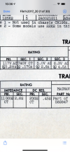
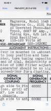
I found a second, more detailed, source of info on this model (Howard Sams & Co. Photofact* Folder, April 1947), which also specifies 30mfd/450v & 10mfd/450v caps for this location.

The unit’s main power transformer is 117vac (pri.), with 740v/ct (sec. 1), so 370v going to this cap. Bench test confirms this. A 20% margin of error would bring that up as high as 444v.

The unit itself is rated 110vac-120vac. Testing what’s coming into my home shows a steady 120vac throughout the day/over multiple days.

My personal thoughts are to go with slightly higher-rated caps if they’re relatively inexpensive and easy to find. Otherwise, as I already have the specified caps on hand, I’m comfortable using them.
 

Attachments

  • 58974DCD-E5C7-4035-BA5E-56C6F960D83C.png
    58974DCD-E5C7-4035-BA5E-56C6F960D83C.png
    484.5 KB · Views: 1
  • 16FC2293-C956-40B9-B06B-BBB06397EB74.png
    16FC2293-C956-40B9-B06B-BBB06397EB74.png
    412 KB · Views: 1
  • C1403C90-F1C4-418C-A8E4-98006D820454.png
    C1403C90-F1C4-418C-A8E4-98006D820454.png
    481.6 KB · Views: 1
Back
Top Bottom