• The move to the new server is done. There are some software and database maintenance updates in process. This has us passing the hat around to help out. We appreciate any donations. Seriously, even a dollar helps. The payment page may be found here - https://www.audiokarma.org/support.html

Squeals of displeasure from DIY Dynaco ST35 clone

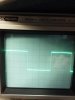
On the phone pic, adjust the scope to the next higher sensitivity range to see your input better, with the tilt on your square waves something looks wrong at 1K. Is the common lead of the opt grounded? Do you have a 16 ohm load resistor connected? You should be using a higher signal input and output, you want about 5v at the output at the 8 ohm tap
I didn't see it in the text, I may have missed it, Is the driver board a SCA35 also?
try removing C3 from the board. C3, C6 and C7 are all transformer dependent C1, C4 and C5
might need to be increased to flatten the tilt, Dave would have a better idea than I for sure.

I'm using the 8ohm taps, and I have 8ohm/100w resistors as dummy loads. The driver boards are ST-35 (not SCA-35). I'll take a look at those cap values next. Thanks for the input.
 
yeah something about that scope response looks wrong. This is what my Magnavox with the Edcor iron does at 1kc. Not sure precisely the output level here, but its probably about 1v p-p. I'd expect to see something a whole lot closer to this on yours.


20170128 1kc square.jpg

Are both output tubes actually conducting? LF response that limited almost acts like a massive imbalance on the output side. The asymmetrical waveform also just doesn't look right to me.

Another thought. With the feedback disconnected, what does it look like at the grids of the input tubes? You should see equal but opposite drive. Quick and dirty way to prove that is to just sum the two channels on the scope. If you get basically a flat line, the inverter stage is happy. It never goes quite perfectly flat but it should be very close.

Totally random thought, maybe ohm from center tap to the screen and plate taps to see if they seem properly placed. The screen tap should be less DC resistance than the plate one. I remember someone on here, maybe kward, had an Edcor with the screen and plate leads reversed.
 
Another thought. With the feedback disconnected, what does it look like at the grids of the input tubes? You should see equal but opposite drive. Quick and dirty way to prove that is to just sum the two channels on the scope. If you get basically a flat line, the inverter stage is happy. It never goes quite perfectly flat but it should be very close.

Grids of which tubes? The 7247? You mean at the input? or the grids of the power tubes after the phase inverter? Also - how would I sum the 2 channels on the scope? I'm a novice in scope usage, please forgive me.

But yeah, both tubes are conducting, and both channels show the same amount of craziness.
 
Totally random thought, maybe ohm from center tap to the screen and plate taps to see if they seem properly placed. The screen tap should be less DC resistance than the plate one. I remember someone on here, maybe kward, had an Edcor with the screen and plate leads reversed.

They seem correct - ~74R on the screens, ~170R on the plates.
 
ok, ohm reading sounds reasonable then. If you go the other way, say with one probe on the blue lead, does the resistance increase as you go from blue-white to red to brown-white to brown? Just in case they switched the brown/white and blue/white internally. Probably not it, but lets just rule out the easy to check stuff.

Grids of the 6bq5 tubes on one channel.

I don't know your scope specifically, but if its a multichannel input, there is usually some way of adding the inputs. My old dinosaur is a 2 channel, and to add them you simply press "ch1" and "ch2". Otherwise you get one or the other on the screen. Quick look at pics of yours shows buttons for 1 and 2, and a "math" button. Wild guess but that will do it, unless you have to tell it to add instead of subtract the channels. You do need to have both channels set to the same v/div setting or it won't work correctly.
 
Back
Top Bottom