• The move to the new server is done. There are some software and database maintenance updates in process. This has us passing the hat around to help out. We appreciate any donations. Seriously, even a dollar helps. The payment page may be found here - https://www.audiokarma.org/support.html

Sruddy's FM-200-B Restoration Thread

sruddy

AK Subscriber
Subscriber
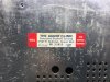
This will be the companion to the X-202-B I just restored. First off the serial number is 20296A so I assume it's a very early model. Problem is I can't find any service manual for anything lower than 30000. Can anyone help me with that. Also since there is no kit I would like to hear what you all would replace and which components would benefit from high end, low noise, ect, versions. I have a new CF manufacturing multi stage can that I can use but that's about it. I purchased some fuse lamps from Parts express but it turns out they are fatter than stock. I ended up breaking the Bakelite holders. Luckily I have a FM-200 that I can steal a pair from. Hopefully Bakelite will glue easily. FWIW I have tried the LED replacements and don't like the white versions. I should have known better and ordered the warm white. They are on the way and I think I will really like them. No need to paint the glass tube as they are directional and they should last my lifetime! :-)

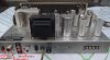
Here are some before photos. Not nearly as nice as the X-202-B. Looks like some of the anodizing has been rubbed off, the knob brights are beyond help,and the chassis has black spots that won't come out. You can see it has seen a bit of moisture as the rivets are rusty. Hopefully the mica caps in the IF transformers are ok.

DSCF5506-2.jpg


DSCF5503-2.jpg


DSCF5502-2.jpg
 
Register to hide this ad
Looks nice, but an odd observation. Why the Dymo label for the serial number applied right next to the serial number?

Is the SO-239 connector standard on these? Can't honestly say I've ever seen that used for an FM tuner before. I've also never seen it used on something that wasn't 50 ohm input.
 
Looks nice, but an odd observation. Why the Dymo label for the serial number applied right next to the serial number?

Is the SO-239 connector standard on these? Can't honestly say I've ever seen that used for an FM tuner before. I've also never seen it used on something that wasn't 50 ohm input.

I thought that was a bit strange too. Maybe someone had bad eyesight. The same connector is on my FM-200.
 
FISHER did the SO-239 on a few of the high end tuners mainly the FM200B, and FM-1000 I believe. As the FM-1000 was the consumer version of their FM broadcast (I'm fishing for the correct term) check tuner, it makes sense to have the SO-239 on it. The FM200B quite possibly was used in the FM Stations as a cross check tuner so had the SO-239 also. I can't remember what they called the tuner the stations used to check their broadcasts.
 
I'm working on the power section first and have a CE Manufacturing 40/40/40/40 350v capacitor on the way. I have no idea what to order for the rectifier so I could use some help. I am working with a schematic with higher serial number that what I have so I hope it will work for everything except the stereo relay. The rectifier is marked SRI which I assume stands for selenium rectifier I. Unless I'm missing it the parts list doesn't have a SRI. It does show CR1 as Diode Varicap, type SC 20, 6.8 and CR2,3 diode type 1112, are these the rectifier parts? What should I order?

Thanks!
 
FISHER did the SO-239 on a few of the high end tuners mainly the FM200B, and FM-1000 I believe. As the FM-1000 was the consumer version of their FM broadcast (I'm fishing for the correct term) check tuner, it makes sense to have the SO-239 on it. The FM200B quite possibly was used in the FM Stations as a cross check tuner so had the SO-239 also. I can't remember what they called the tuner the stations used to check their broadcasts.

So Larry for today we would use the 300 ohm terminals with a 75 to 300 ohm converter if needed?
 
You don't need a converter to use 300 twin lead. The 2 screw terminals to the side of the SO-239 is for 300ohm twin lead. OR find a SO-239 connector and solder your Co-AX to it on one end, and an "F" connector or whatever connector your system is using and run to either the antenna or a splitter. Then move the switch to either 300 or 72 ohm.

Most antenna's today use a 75 (72 is close enough) coax with an "F" connector. Very few use the 300ohm twin lead. Personally I like the 300ohm twin lead as I can pull more clean stations from a "T" dipole than most of the cheap chinese built antenna's at the big box stores. Twin lead can be used for outdoor antenna's also. CABLE Co's are one of the big reasons for using COAX all over the place. The problem is they are using a different impedance COAX for TV and internet than radio uses.


FM-200B antenna layout.JPG
 
You don't need a converter to use 300 twin lead. The 2 screw terminals to the side of the SO-239 is for 300ohm twin lead. OR find a SO-239 connector and solder your Co-AX to it on one end, and an "F" connector or whatever connector your system is using and run to either the antenna or a splitter. Then move the switch to either 300 or 72 ohm.

Most antenna's today use a 75 (72 is close enough) coax with an "F" connector. Very few use the 300ohm twin lead. Personally I like the 300ohm twin lead as I can pull more clean stations from a "T" dipole than most of the cheap chinese built antenna's at the big box stores. Twin lead can be used for outdoor antenna's also. CABLE Co's are one of the big reasons for using COAX all over the place. The problem is they are using a different impedance COAX for TV and internet than radio uses.


View attachment 678086

I have 75 ohm coax coming from my antennae. I was thinking it would be easier to use a converter and hook it to the 300 ohm terminals. I didn't realize I could use the SO-239 since it was off a few ohms. I may still use the 300 ohm input just for the convenience.
 
While waiting on the parts I decided to clean the dial glass and repair the broken lamp holders. I was very careful on the glass cleaning but still managed to erase some of there small lines. I almost crapped when I saw the damage. I have cleaned glass before with no problems. On my first restore I did a R-20 and used Windex on it with no problems. This time I was very paranoid so I just put one drop of Dawn dish washing liquid in a bowl and tested the part number on the side. I rubbed hard and it didn't come off. I figured I was good but after my very gentle cleaning of the rest, with a microfiber cloth, a few of the fine lines lifted. I couldn't believe it. Maybe the dish washing liquid was to strong? I am going to try and paint them back in and will post my results.

Thanks to Dave the reversing of the lamp holders was an excellent fix. I also used some epoxy and glued the bakelite that I snapped trying to put the wrong size lamps in. I used the Warm white LED and really like them. They are directional so you can rotate them just the way you like and I think the color matches the original lamps well. I have tried the white versions and didn't care for the color.

Also I will try and find something to stain the area on the faceplate were the anodizing has come off. Hopefully the aftermarket faceplates will be ready soon. I also need knobs if anyone has some for sale let me know.

_Z8A0815.jpg


_Z8A0829.jpg


_Z8A0832.jpg
 
Any time you convert impedance you have a loss. Fair bet that internally there is a 300 to 75 ohm transformer already inside. It would lose even more to go from 75 to 300 externally just to have it convert back inside the chassis. If your existing antenna cable is a 75 ohm with the typical F connector, you can use something like this to make it plug into the SO-239

http://www.amazon.com/coaxial-adapter-female-PL-259-connector/dp/B00CXNG9O8

For whatever reason the male end of this connector is a PL-259, the female is SO-239. Nothing like numbering consistency to make this clear as mud.
 
Any time you convert impedance you have a loss. Fair bet that internally there is a 300 to 75 ohm transformer already inside. It would lose even more to go from 75 to 300 externally just to have it convert back inside the chassis. If your existing antenna cable is a 75 ohm with the typical F connector, you can use something like this to make it plug into the SO-239

http://www.amazon.com/coaxial-adapter-female-PL-259-connector/dp/B00CXNG9O8

For whatever reason the male end of this connector is a PL-259, the female is SO-239. Nothing like numbering consistency to make this clear as mud.

Thanks!!!
 
If you have an old CB antenna with the pl-259 connector on it, check fit it. If it fits, de-solder it from the CB antenna and solder it on to the Antenna. Problem solved.

The 200B has a converter on the 300ohm side between the input screws and the 300-72ohm switch. So no need for a 300-72 ohm or vice versa balun. Just connect direct to the side you have already run.

ScreenHunter_274 Jan. 25 18.42.jpg
 
Last edited:
Sruddy, that's looking good, there are a few knobs on that auction site as we speak. (No Affiliation). Your dial glass isn't that bad, i wouldn't loose any sleep over it, you did good! AL
 
4 section Can caps generally go for between $36.00 and $48.00. The values and voltages are geared more for Guitar amps not audio gear, unless you go with a custom can cap. Also some are extremely hard to de-solder, so re-stuffing in place makes sense.

4 radial Electrolytic caps of sufficient value, voltage, and a small enough casing, can be had for less than $10.00. If you use a multi tool in the saw mode you don't have to remove the bottom of the old can from the chassis. Remove the top, gut it, install the 4 caps (with insulation on all leads, drill 5 holes in the bottom (1 for each section positive and 1 for the combined ground) and solder them all up.Use JB WELD on the top/bottom joint and clean up the rough spots. And you're done.

If you have an old CB antenna with the pl-259 connector on it, check fit it. If it fits, de-solder it from the CB antenna and solder it on to the Antenna. Problem solved.

The 200B has a converter on the 300ohm side between the input screws and the 300-72ohm switch. So no need for a 300-72 ohm or vice versa balun. Just connect direct to the side you have already run.

View attachment 679194

Thanks for the confirmation on Gadget's hunch. I'll order the adapter so I can run my coax directly to the SO-239. BTW I always take the manual into photoshop and combine the schematic into one page, and print on 13 x 20 matt card stock. I was unable to do this as the pdf has had a security code attached to it. I have tried vintageshifi and fisherconsoles and both service manual downloads have need a password to open in PS. Let me know if you have a different source and I will give that a try.
Update: This site has a few service manuals as a sticky. They have 2 for this model and they are not locked. I will post a download once I get the schematic done.


Sruddy, that's looking good, there are a few knobs on that auction site as we speak. (No Affiliation). Your dial glass isn't that bad, i wouldn't loose any sleep over it, you did good! AL

I saw those and bid on one. I found out today both auctions the seller had going, I think a total of two knobs in each, went for a total of over $170!!!!! :yikes: Are you kidding me??!! That's over half of what I paid for the tuner. Is this the normal going price for original knobs? They didn't even look like they could be brought back to like new. I have already tried one of the aftermarket caps. They were the ones with a recessed indicator. They had a very nice finish that matched the original double diamond, or star reflection but they were not deep enough and left space between them and the knob. The ones from China look like a great match as far as the shape and size however they looked to be tooled badly and don't have the nice original double diamond/star reflective surface. So I'm in the need of some knobs. In the meantime I can pull a set from a FM-200. They don't have brass caps though, and this will be sitting next to my X-202-B and they should look similar.

Thanks Al, I guess you just never know what will happen with the printing. I once ruined a glass using plain water. Now I know just because your test point passes doesn't mean all the printing will pass.

I have the all the parts for the power section ordered but still want to replace the 20 caps that aren't ceramic. I would like to improve the sound and or performance if possible. What brand of caps do you all like. Up until now I have used orange drops or gone with kits from Jim. Jim has no kit for the FM-200-B.

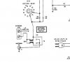
Also it looks like there are two filter caps on this tuner. This is the first time I have worked on a unit with this design. I'm assuming it is this:

  • An improvement in circuit design is where an AC radio has two line-to-ground capacitors (see below schematic) to filter both sides of the line. This will give you better power line filtration and you don’t have to worry about polarity when you plug in your radio. However, let’s not complexly knock the single bypass design as some early AC tube radios used NO line filter capacitors at all.
twobypass.jpg
Here is my schematic. I'm assuming it is essentially the same as above.
They look to be .01 600v. Shall I use my usual X1 Y2 safety caps?

FM-200-B-safety.JPG
 
Last edited:
Yep. the usual X-Y caps are now mandated BEFORE the primary winding as they fail OPEN, not fail closed like normal caps. Electrically both schematic designs are the same as far as the caps go. So anytime you replace BEFORE the Primary windings use the X-Y caps.
 
Yep. the usual X-Y caps are now mandated BEFORE the primary winding as they fail OPEN, not fail closed like normal caps. Electrically both schematic designs are the same as far as the caps go. So anytime you replace BEFORE the Primary windings use the X-Y caps.

got it,Thx!
 
Thanks for the links. I'm going to give them a try. I saw a Fisher tuner with a green lit dial that looked pretty good in a photo. They must have used the green LED's.
 
Back
Top Bottom