• Please note that Audiokarma will be offline briefly for updates early on Monday morning, September 28th.

Stabiline Voltage Regulator - with Thylatrons!

Bradbrews

Super Member
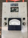
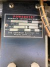
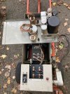
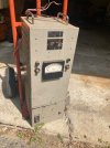
I was recently given this beast, though I had to haul it out of a basement and heave it into the car. (I should have declined until I came back with a hand truck/dolly)

It’s a Model S-290, a 2 KVA unit with a motor driven Powerstat!
The only issue is a broken fuse holder. I briefly tested it and it worked!
There are no indications of what size fuses should be used in the control circuits. The one on the left has a 3amp fuse, so I tried one of those in the missing one as well.
Does anyone know what size fuses this thing is supposed to have?
It does seem to make an audible humm when operating- aside from the motor adjustments.
Are there any practical uses for this thing today?
I suppose I could use it for my tube amps and ditch the bucking transformer…IMG_0074.jpeg
IMG_0111.jpeg
 

Attachments

  • IMG_0113.jpeg
    IMG_0113.jpeg
    250.8 KB · Views: 26
  • IMG_0116.jpeg
    IMG_0116.jpeg
    277.2 KB · Views: 23
  • IMG_0115.jpeg
    IMG_0115.jpeg
    216.4 KB · Views: 26
  • IMG_0112.jpeg
    IMG_0112.jpeg
    322.9 KB · Views: 25
Register to hide this ad
Well it worked for a while…
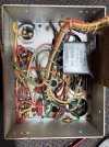
I put a new fuse holder in it and wired it up a bit better and gave it another go.
This time it started hunting and never stopped.
Now it’s just another thing that needs repair…. The capacitors are high on the list of potential issues. I just hit them with full line voltage when I tested the unit as you can’t really bring a voltage regulator up on a variac…
 
Cool looking piece. I've finally developed the ability to walk away from things like that. Too little space/time/motivation to bring everything I find back to working at this point. Not long ago, I, too, would have hauled it home. Good luck with it.
 
General Radio Corp. made several motorized Variac line voltage regulators. They invariably need some new caps to work right. IMO, they're pretty great because they always produce a sine wave and they don't hum (much). Most other regulating schemes don't produce a sine wave and those stupid Sola constant voltage transformers not only hum, but they also run hotter than the dickens. They also need the load to be within a specific range.
 
Spent some time on this yesterday and it’s working again!
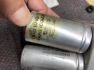
I checked the two can caps and the 2X 0.25 uFd and they were all good.
I cleaned the contacts on the tube sockets, the relay contacts and the black wrinkle finish voltage sensor.
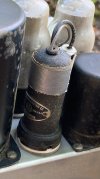
That may have been where the problem was but I don’t really know. It’s been repaired sometime in the past and has had a 6.3v light added to one of the two circuits. To do that the housing was opened up and the recrimp holding the cap onto the base came loose when I was trying to remove it. After removal I pulled the cap off completely and dislodged a wire that went to the bulb and a wire wound resistor.
It took some doing but I was able to get the broken wire out of the tube pin and installed a new one.
Upon reassembly everything is fine!
I assume that the bulb acts to vary the resistance with voltage changes more than the wire wound resistors?
What would have been there in place of the bulb, originally?

Also I don’t think I’ve ever seen can caps in the 4uFd, and 1 uFd size before. They seem much larger than an electrolytic would be. I suspect that they are likely filled with oil -probably containing pcbs…
Since they work fine I think they are plenty safe enclosed in the unit.

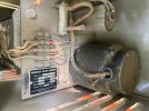
To open up the control box I had to cut not one but two of these lead wire seals stamped with the Superior Electric logo.
I’m the first one to break the seal, and I doubt it was really necessary.
 

Attachments

  • IMG_0240.jpeg
    IMG_0240.jpeg
    221.4 KB · Views: 14
  • IMG_0241.jpeg
    IMG_0241.jpeg
    248.8 KB · Views: 13
  • IMG_0243.jpeg
    IMG_0243.jpeg
    183.2 KB · Views: 14
  • IMG_0244.jpeg
    IMG_0244.jpeg
    330.5 KB · Views: 12
without a schematic its hard to guess exactly what the lamp is doing, but incandescent bulbs have a positive temperature coefficient, meaning the hotter they get, the higher the resistance is. Sometimes that property has been used to stabilize circuits, possibly what its doing here. Trick with that is you need a specific lamp type and sometimes it needs to be a selected part to confirm its got exactly the right properties.

it may have had a bulb originally, but just living inside rather than on the front panel. Maybe someone put it on the front to allow for easy replacement. If it was originally hidden inside, probably was done so that it didn't get just any random bulb that fit the hole stuck in there.
 
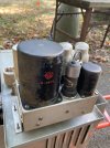
I should have taken a better picture of plug in unit. It’s this one with the wires coming out of the top and the bulb taped to the side. Originally it held everything inside it. The bulb was the “fix”.IMG_0115.jpeg
 
I thought you were referring to the front panel lamp as the add-on part but still probably being used in the same way. Normally that sort of thing would require replacing that plug-in unit and i'm sure that drilling a hole and taping a lamp holder to the side was a lot cheaper than buying that part, if it was even available when this fix was made. Looks like a hack but I bet it works fine.
 
Back
Top Bottom