• The move to the new server is done. There are some software and database maintenance updates in process. This has us passing the hat around to help out. We appreciate any donations. Seriously, even a dollar helps. The payment page may be found here - https://www.audiokarma.org/support.html

Starting First Restoration of Sansui 1000a

Perkinsman

"I've never met a fixer that I couldn't break"
I've read thru a number of posts here see that this forum has some very experienced 1000a people. I wanted to check in before I get too far along in restoring this unit. I've been mostly working on Marantz units but I also work on tube amps and understand the voltage dangers present and will be discharging the main caps each time I shut down.

So far, I've just replaced the aluminum ecaps with new Elna Simlic's/Nichicon of higher voltages to exceed the SV's I've seen printed on the original caps.

I don't have much experience with PIO caps and noticed that there are quite a few in this unit. I happen to have a good number of Russian pio's of the correct value so it's an easy fix if needed. Do these routinely get replaced as do the aluminum ecaps during restoration?

Are replacement cap cans readily availbable for the main caps or do most people restuff the old ones?

Are there any specific components other than what I've mentioned that should be replaced (or ones that should NOT be replaced) on this unit?
 
Last edited:
Register to hide this ad
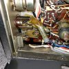
I didn't change out anymore components today but I spent a good part of the day cleaning up the unit, including the controls, switches, sockets, chassis, and lubricated the dial string path. It gave me the opportunity to closely inspect the components and wiring. After a good cleaning, I powered up on the variac. I'm barely getting sound on am/fm and after exploring, I may have found out why. It appears that some of the wiring to the Band Selector & the Selector has been separated. There are 2 fine red wires, 1 fine white wire and a thicker gauge dark blue wire that detached from one or both of the 2 Selector discs. They are closest to the Band Selector so I'll start there first. I also found that the AFC toggle switch above had a detached wire.
 

Attachments

  • s6.jpg
    s6.jpg
    32.3 KB · Views: 69
  • s7.jpg
    s7.jpg
    69.2 KB · Views: 70
  • s8.jpg
    s8.jpg
    76.7 KB · Views: 71
Last edited:
Main filter caps. The 4 section towards the front can be replaced from stock @ Antique Electronics Supply. The rest can be stuffed. The Doubler supply Can's I used 470uf 400V Nichicons (I don't know the #'s as it was 10+ years ago.

Replace each and every PIO in it. They have the unerring tendency to go POP, and spew contents all over. As the 1000A tends to being heavily on the bright side, try to limt the Russian PIO's. Mix up with Yellow I.C. caps and or orange drops(O.D.'s). Watch the replacements on the output coupling caps. They are .030/250V. Most .033uf/400v (with the exception of O.D.'s) will fit in the same spot. Don't go larger or you'll be using a crowbar for a shoehorn.:naughty::naughty:
 
Thanks for those specifics, I worked on the messed up wires attaching to the selectors all day and still not sure where 2 wires go. It's like many of the wires attached to the selectors had been rubbing against the metal on the discs to the point where insulation wore off and abraded until the wires actually detached.
I need to ask for help reading the selector part of the schematic.
 
Need a good picture of one thats all original?

Mine is handy since restoring it and could do that no problem.

Thanks for your offer, figured it out after getting a good look under the bass & treble selectors, I found 2 little pieces of the 2 wires still attached to a nub on each selector but I wouldn't mind seeing some pics of the underside in general. My friend has a 1000a that a recap professionally done and it has a mix of 3 or 4 different make caps, a few little yellow IC's, some little brown chicklet types & little blue chicklets of the same values as the original oil caps. Aren't they all just poly film caps or is there a difference?
 
Glad you got it worked out. These do have some fine wires on the controls don't they.
Caps sound like a mix of what the restorer your friend used had in stock or could source in the right values that will fit in the very busy space underneath these. I did the same thing.
Important thing is getting rid of all the old oil caps and big cans on top. I resuffed two and replaced the voltage doubler caps with new ones in the right value but higher voltage rated sourced locally.

20200803_084944.jpg

I moved the big power transistors based on the excellent thread posted by forum member Larryderouin. Helps get rid of a lot of extra heat around the power transformer. Recommend doing this mod. Larry gets full credit. :thumbsup:
http://audiokarma.org/forums/index.php?threads/1000a-power-resistors.536768/
20200720_090601.jpg
 
Main filter caps. The 4 section towards the front can be replaced from stock @ Antique Electronics Supply. The rest can be stuffed. The Doubler supply Can's I used 470uf 400V Nichicons (I don't know the #'s as it was 10+ years ago.

Replace each and every PIO in it. They have the unerring tendency to go POP, and spew contents all over. As the 1000A tends to being heavily on the bright side, try to limt the Russian PIO's. Mix up with Yellow I.C. caps and or orange drops(O.D.'s). Watch the replacements on the output coupling caps. They are .030/250V. Most .033uf/400v (with the exception of O.D.'s) will fit in the same spot. Don't go larger or you'll be using a crowbar for a shoehorn.:naughty::naughty:
 
Can you tell me where the doubler (470/400) caps are you mentioned, I can't find them and they're not on the parts list. I'm also looking for the .03/250 coupling caps in this birds nest. Additionally, are the screw in 6.3v/.15a pilot bulbs the same ones Mouser sells listed as part #560-40?
 
Last edited:
Hoping to hear from someone regarding my previous thread questions before I put in a Mouser order.

I also found a burnt resistor but need help id’ing it. Can’t read a value or find it on the schematic. It’s located on the bottom of the board directly behind the Balance pot. There’s only 3 resistors on the bottom of the board, the other 2 are 100k.
 

Attachments

  • 87ED3618-5C90-49F2-9EDD-DF098A66CB00.jpeg
    87ED3618-5C90-49F2-9EDD-DF098A66CB00.jpeg
    147.9 KB · Views: 44
  • 43553240-62A2-4A78-802B-26C022FFD0C0.jpeg
    43553240-62A2-4A78-802B-26C022FFD0C0.jpeg
    190.4 KB · Views: 47
You've got an early version, similar to what mine was originally. It can be converted to a 4 pot, but if you're not comfortable doing the mod, just run it as a single with tightly matched 7591's. The resistor you show as burned is on the MPX board. Mine is in storage about 20 miles, but i have to clean it out anyway, so I'll get it this weekend. 4 pot schematic below. There are 4-5 different schematics for the 1000A so be careful as each has slightly different stuff.

The resistor in question in post 10. Is it on the 1 pot 1000A or a 4 pot 1000A.

Doubler caps are the two outermost CAN CAPS directly in front of the POWER Transformer. Single Value 200uf, 300wv (IIRC). 330uf @ 400v or 450V is good. You want some voltage reserve (headroom) as the operating voltage on these is very close to original rating. Stuff the originals. These will work well in the Sansui and fit inside the can's.
https://www.mouser.com/ProductDetail/Nichicon/UPT2G331MRD?qs=B2feYorFvuLwNpXoZpY5xA==
 

Attachments

I used JJ 50/50 500 volt C-EC50-500
JJ 40/20/20/20 500 volt C-EC40-20X3-500
(2) S-H128 1.5” clamps from AES on my 500a

Don’t know if the doublers are the same in the 1000a
Trying to find pics of the other cans I used. I didn’t restuff
 
You've got an early version, similar to what mine was originally. It can be converted to a 4 pot, but if you're not comfortable doing the mod, just run it as a single with tightly matched 7591's. The resistor you show as burned is on the MPX board. Mine is in storage about 20 miles, but i have to clean it out anyway, so I'll get it this weekend. 4 pot schematic below. There are 4-5 different schematics for the 1000A so be careful as each has slightly different stuff.

The resistor in question in post 10. Is it on the 1 pot 1000A or a 4 pot 1000A.

Doubler caps are the two outermost CAN CAPS directly in front of the POWER Transformer. Single Value 200uf, 300wv (IIRC). 330uf @ 400v or 450V is good. You want some voltage reserve (headroom) as the operating voltage on these is very close to original rating. Stuff the originals. These will work well in the Sansui and fit inside the can's.
https://www.mouser.com/ProductDetail/Nichicon/UPT2G331MRD?qs=B2feYorFvuLwNpXoZpY5xA==[/QUOTE

Wow, thanks Larry, very kind of you to check the resistor on your unit. The burnt resistor is on the unit I'm working on, the 1 pot 1000A. I just replaced the doubler caps and the other cans today, so that completes all the caps in the unit. Other than the resistor, I haven't been using a schematic yet, just replaced the caps with the same values or close. I was going to set bias and dc offset tomorrow, so I was going to look for a 1 pot schematic on hifiengine or the AK database. Are there any other adjustments to check?
 
Wow, thanks Larry, very kind of you to check the resistor on your unit. The burnt resistor is on the unit I'm working on, the 1 pot 1000A. I just replaced the doubler caps and the other cans today, so that completes all the caps in the unit. Other than the resistor, I haven't been using a schematic yet, just replaced the caps with the same values or close. I was going to set bias and dc offset tomorrow, so I was going to look for a 1 pot schematic on hifiengine or the AK database. Are there any other adjustments to check?
 
No dc offset. Just set the bias. Did you add cathode resistors (10ohm 1/4W to pin 5 and ground). If so you can get a global bias for all 4 off the highest reading tube, and even pair the tubes for bias. read off the ma on the highest tube and use that as your bogey tube for now. Your target watts is approx 75% of total dissipation (about 14.75W on thehighest tube.)
 
Serial 16027920 Feb 1966. Your's should be close.

The burnt resistor on the mpx board is R185. 3.9K (3900Ω) 1/4W.
ScreenHunter 215.jpg
R185 was later discontinued. But if you have it in your 1000A keep it in.


R185 is the Blue resistor roughly in center of Picture.
20200808_212443_resized.jpg


R185 to left of GREEN 10W 8ohm
20200808_212455_resized.jpg


Screen stability resistors 100Ω1/4W (very highly recommended), Cathode resistors 10Ω 1/4W, IBAM to bias 4 tubes,
Power resistor mod, I forgot I had K42Y .33uf 400V coupling caps stuffed in it. My 1st receiver overhaul. I must have done something right as it runs as good as my Fisher 800c's. A lot of the mods for the FISHER will translate to the 1000A without a lot of difference.


20200808_212544_resized.jpg

20200808_212650_resized.jpg

20200808_212659_resized.jpg

Guess I'll have to break down and scrub the MPX board. 1st time open in 4 years.
 
Thank you for taking the time to get your unit and taking all the pics. Very neat job, wished mine looked like that. Good to know about not having to do dc offset, I do them on all the Marantz units, is it because most tube units are cap coupled?

My to do:
1. 10 ohm (pin 5 to grd)
2. 100 ohm (screen to where?)
3. Power resistor Mod (I'm curious why the resistors are on the tube side, why not the opposite cooler side)?
4. R185 3.9k ohm
5. 4x20uf can
6. Bias (Where is this procedure for the 1 pot model)?

Btw, I ran into a problem along the way and lost volume on the right channel. It occurred after replacing the pio's with new caps. Where is the right amp circuit in this unit and what would be the most likely place to look?

Edit: 1, 4 completed
 
Last edited:
Back
Top Bottom