• The move to the new server is done. There are some software and database maintenance updates in process. This has us passing the hat around to help out. We appreciate any donations. Seriously, even a dollar helps. The payment page may be found here - https://www.audiokarma.org/support.html

Statesman S-70 Console/SA100/202T--20 questions

FireGuruMN

Active Member
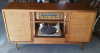
I have a beautiful 1960 console stereo if working condition. But I need to do the basics:
Make it safe
Make it sound good
Make it stay that way
Before (and after--it's just perfect the way it is)
upload_2019-4-24_17-53-1.png
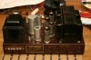
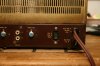
First the SA100 amplifier:
1) It still has several of the original Fisher tubes. I have not run any of them through a tester but I don't want to use them. I prefer to preserve them and burn through some less historic tubes. From my internet searching it seems that Sovtek EL84M's are the preferred choice. And a Sovtek rectifier tube should be fine also. I think I will use the Fisher phase inverters as they should last for ever anyway and replacements are expensive. . .
2) All the "brown drops" are mylar capacitors. So no need to replace them, right? Maybe there are better choices available today? I like Solens.
3) What do the 4 AC/DC pots do? I plan to leave them alone, right?
4) Is there a schematic to provide individual bias for each tube?
5) Replace the 3 red electrolytics and the multcap can. Any preference for buying a new multicap versus putting caps under the chassis?
6) Should I add a "surgister"?
7) Changed to a grounded cord so I don't have to worry about polarity?
8) Replace the selenium diode.
9) One rebuilder was very worried about grounding to the copper chassis developing a resistance due to dissimilar metals over time. Should I worry too?
There were burn marks on the back of the cabinet where the amplifier was located so there has been some drama over the years.
Before:

upload_2019-4-24_18-11-49.png
The 202T tuner/preamp:
10) Again, mylar caps all over so no need to replace them.
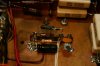
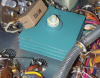
11) Selenium rectifier has to go for safety reasons. Any recommendations for a silicon part? I have a Onkyo M504 parts unit with some monster rectifiers I could use.
upload_2019-4-24_18-14-46.png
12) Lots of multican caps in this preamp. Maybe leave them alone or is that just asking for trouble?
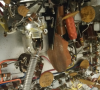
13) Remove the pottery. yes, someone put a piece of terra cotta pottery near the power switch for some reason. Along with a piece of metal. Place jokes about leaky pottery here. Anyone know what that could be doing there? The power switch seem somewhat loose. It is tight to the face plate but wiggle some when turning on/off.
upload_2019-4-24_18-18-12.png
14) Remove the death capacitor. Should I replace it or just put in a grounded plug so it is not necessary.
15) Display bulbs are burned out. Anyone have a part number?
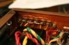
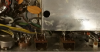
16) There is a black bare wire hanging out of the shielded area in the back. Any thoughts? its right below the round ceramic cap in this picture.
upload_2019-4-24_18-23-55.png

Speakers:
17) I have new Solen capacitors in hand. Are there any resistors other than the potentiometers?
18) I heard some concerns about the horn tweeters being problematic. Are they valid concerns? I have not heard the speakers except with a poor FM signal so I cannot say how they sound?

Turntable:
19) I'm just going to make it look nice but probably not use it. Anything necessary to make it safe?

General:
20) How do I get rid of 60 years of cigarette smell?

Thanks for making it through all 20 questions. This is my heaviest piece of audio yet and I own some Phase Linear monsters! The best thing is that my wife wants this in the living room as soon as the cigarette smell goes away. How many AK members have had that happen?:beerchug:
 
Register to hide this ad
On the SA-100, my suggestion is to read this:

Improving the Fisher SA-100 with EFB II

I have two SA-100's, both EFB'd. In short, the modifications reduce stress on the power tubes, and eliminate most of the power resistors that cook everything in their path. You've already indicated evidence of that.

My own effort is detailed here:

Here We Go Again: Fisher SA-100

If you decide to go that path, most of your questions/concerns would have been addressed.

BTW: I was brought up with that console. My pops put it together sometime in '61, maybe '62. He had the 400 receiver in there with some Electro Voice horned speakers. His genius son dumped the antique receiver and the old fashioned speakers for some modern stuff sometime in '84-'85. Now said son's house is full of things Fisher.

Go figure.
 
STRIP EVERYTHING OUT OF THE CASE. Take it outside in the SUN, and wash it inside and out (start with DAWN and HOT WATER). Use the minimum required to clean off all the old dirt,dust,etc. Rinse and AIR DRY. When it appears dry, spread baking soda (good old Arm & Hammer) all over the interior(as it's not sealed this is where the smells eminate from). Throw in a couple more boxes (open) and seal up the whole thing with painters plastic and Seal it up air tight. Put it back in the garage and leave the cabinet stew for a week or two, while you work on the components. Alternately you can use 1 lb of coffee grounds (use the store brand stuff, no need for Starbucks here....unless the wife insists!) vs the baking soda.
 
SA-100
1.) The EL84M is an ideal tube for the SA-100. Get them from a reputable dealer. I recommend Jim McShane. He'll test the crap out of the tubes and you'll get a good matched (for true output, not just emssions or gm)QUAD. The Sovtek GZ34 has done Yeoman duty in my FISHER's that use one. Does quite well.
2.) replace the Brown Mylars. They tend to leak electrically. (commonly referred to as "DOG TURD's"
3.)AC/DC pots balance and bias the output tubes. Don't touch them YET! Unless Dave Gillespie has a better setup for bias and balance, I'd leave the circuit alone.
4.) Service manual here............. http://www.fisherconsoles.com/statesman II S70 service manual page.html
5.) I prefer Hayseed Hamfest Can Caps. Then again mostly personal preference as to whether you replace the can in toto, stuff, or individual caps underneath.
6.) Probably as you're gonna replace the Selenium rectifier with silicon.
7.) NO! You can replace the "death caps" with X-Y rated Safety caps and not worry about GROUND LOOPS from a grounded plug. Determine which side the SWITCH IS ON (cord) and mark the plug so the switch side is on the LINE (or HOT).
8.)See #6. And you'll need a dropping resistor, probably in the neighborhood of 27-33ohms 5W.
9.)Chassis is Copper PLATED. Minimal Electrolysis will occur. You're grandkids might notice a very slight bit of corrosion at the ground point 50 years down the road but generally it won't hurt it.

T-202
10.) REPLACE IT! 3A 400V rated is a little overkill, but a good choice for longevity.
11.) Again replace the DOG TURD's
12.) Replace them.
13.) Remove thepottery and check for loose/cold solder connections on the switch/pots. The metal piece may be an RF(EMF) Shield btwn the Volume control/Power switch and the rest of the unit. If it's not soldered down, it's a good bet it's NOT original.
14.)See #7.
15.) Are the lamps tubular or look like a flashlight bulb (bayonet base) If Bayonet base, most likely #1847. If tubular need length and diameter. FISHER used 2 different sizes depending on unit. These can be replaced with LED (Cool White). They are on EBAY.
16.) It's called a "GIMMICK" (SERIOUSLY!!!!) It's a Test point used when aligning the RF section of the Tuner. Leave it alone.

SPEAKERS
17.) Speaker Schematics are in the Service manual. Test them with a VOM. If within 10% OK.
18.) If the Tweeter is a TRUE Horn, shouldn't be any problems. However if it's a cone tweeter, look at the EIA code on the Frame. If the 1st 3 numbers are "220" it's a JENSEN, which is a 95%+ certainty. These don't normally go bad. The one's you're thinking about are the Dome tweeters made by Bill Hecht from 1961 and up to about 1967. The foam disintegrates and they sound like crap. They can be fixed but it's not a job for an impatient person.
19.) The TYPE "A" is a good turntable. Give it a good cleaning, DeGreasing underneath, and relubricate it. the side pushers are very nice for stacking records and they are gentler than a straight drop turntable. Put a new idler wheel on it, and clean the inside rim, and motor spindle with NON-RESIDUE CONTACT CLEANER, and a Green Nylon Scrubbie pad. Oil the motor bearings (TOP and Bottom) with Zoom Turbine oil(Ace Hardware has it). Other lube points get either oil, or White lithium grease. I generally mix 3 parts of grease with 1 part of oil to cut the viscosity of the grease a little.
20.) Addressed in POST #3.

Have FUN! Don't be afraid to ask more questions. We all started somewhere, and you've got one of the nicer '60's.
 
Beautiful console. The Type A is most likely an upgrade as it came out in, I think, 1961. The '61 President had it but the rest seemed to all have the 88. I do like the A better...

Not too many Statesmans around so you have a rather rare unit.
 
Type "A" came out in '61. It was Standard Equipment in the Statesman, Executive and the President. Lower than Statesman had the RC-88. If this is a S-70, then it's a '61 model. The '60 model S-1010 had an RC-88 in it and 100 Mono blocks.

FireGuruMN; Do you have any factory documentation with the Unit. The 60' and 61' are identical except for the phonograph and the amp. The '60 had 2- 100 MONO BLOCK Amps and the RC-88, while the '61 is equipped as your's is with the SA-100 and the TYPE "A" TT.
 
I have to admit that I pretty much wrote the turntable off as eye candy. But I see now that they put a lot of effort into making a quality product.
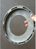
It is a Type A. The platter is removed in this picture. Obviously some foam needs replacing.
upload_2019-4-25_16-49-9.png
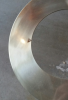
I am totally impressed that the platter is balanced with brass weights:
upload_2019-4-25_16-51-22.png
And has a mark to match up with a mark on the motorized plate so they stay balanced.
upload_2019-4-25_17-6-23.png

By the way, I this the best way to post pictures? I am snipping an image and pasting it into the text. Seems better than uploading high resolution photos and filling up a server with surplus pixels.

The needle looks good:
upload_2019-4-25_16-54-21.png

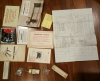
I have a lot of documentation and accessories to go with the turntable and amplifier. Should I submit the warranty card? I will be happy to scan anything and post it in an appropriate place if there is anything of any value in the pile. I love that the free sample of record cleaning cloth was included:
upload_2019-4-25_16-56-50.png

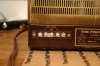
Here is a picture of the data sheet on the back of the cabinet:
upload_2019-4-25_16-58-48.png
Some interesting notes written there. "Dead" on the AM tube. 1/3 and 1/2 on several of the EL84 power tubes. I note that the ones that say 1/3 have been replaced with Sylvania tubes and the 1/2 are original Fisher.

And when talking about quality: It is great that Fisher put the function of each tube on the schematic. I don't recall seeing that in any other manufacturer documentation. And when looking at the schematics in the manual there are text blocks at the bottom of the diagram below the location of each capacitor and resistor which make it incredibly easy to find them in the schematic. I wish that trend had continued for the last 60 years.

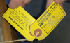
Here is a shot of the inspection tags on the amplifier:
upload_2019-4-25_17-4-30.png
That indicates March 9, 1960 from the "3.9.0" I am guessing. But the amplifier might have been a different date than the rest of the cabinet.

I have to chew through the answers that have been provided.

As for the EFB mod, I tend to steer away of things I do not understand. But at this point I am married and have children so I'm pretty far into things I do not understand so I might go a little farther.
But first I will get it running as it was designed. More questions to follow after dinner.
 
Fire. Rather than try to find foam that is compatible with AUDIO life for the TT, you might try something I did with a Type "A" Mark II I have in my 63 Exec. Scrape off all the foam as best you can. Extrordinary measures are not warranted. Then get some small cell bubble wrap (green stuff @ home Depot is fine. ( Make sure it's small cell!)
I used 3m spray adhesive, but Shoe Goo works fine too. Cover the bottom platter, then lay the bubble wrap (bubbles up) on the platter. Keep your alignment mark visible. Once dry and stuck on, trim to the outer edge of the platter. Lay the upper platter on it and enjoy. Lots less motor noise gets thru on mine now.


Larry
 
Ok, back from buying a new lawnmower. On with things that really matter.

SA100
1) Tubes: Ok, I will go with the Sovtek tubes.
2) Caps: I will replace the dog turds. I've been using Solens but I see people putting in PIO Russian caps. Really? I just finished pulling all sorts of oil caps out of Two Sansui 1000A's. Now I am adding more in to a different amp. I assume these oil caps are better? Where do I get them?
3) AC/DC pots: I will leave them alone.
4) Individual bias: I read Larry's thread about individual bias and adding additional test points. I really don't want to modify the external appearance at this point to add test points. Can I put them inside the amp? And I find it interesting that they have shorting jumpers on the test points. Is there some instruction about how to use the jumpers? When are they removed and when are they in place. I added 10ohm resistors to my 1000a and no one said anything about any jumpers. Yes, I am sure my newbie status on tubes is showing through. So while I am at it. Someone point me to an explanation of why I need to add 100ohm screen resistors.
5) Multi Cap Cans: I have a CE 40-40-20-20 that I misordered a while back. Is 20 close enough to 10 for this application?
6) I will add a surgistor.
7) Power cord: Ok, I will keep the original cable. I don't see where there is a death cap in the SA100 but looks like there is one in the 202.
8) Diode: ok, replace the diode and add a dropping resistor.
9) Electrolysis: No worries for now.

202-T:
10) Rectifier: I will look for a less beefy replacement. From what I see in the schematic that rectifier is powering the heaters on the phono section and the bass/treble controls. Then there is a rectifier tube for the other heaters. Is the selenium rectifier making cleaner power?
11) Dog turd caps: There are WAY too many dog turds in the 202. Can I just replace the blocking caps and move on? I won't be using the radio very much.
12) Multi can caps: again, that's a lot of caps. I think I will do my first "under chassis" installation attempt on this one. I will have to see how much room there is first. I've never tried stuffing either. maybe a mix.
13) Pottery: I will investigate for loose connections in this area.
14) Power Cable. ok, I will leave it in place and find a safety cap. Did you see the tag I posted that describes reversing the polarity of the plug to minimize buzzing. I had a friend a long time ago with a very old TV. If they plugged it in one way everything was fine. If they plugged it in the other way it would blow a fuse every time they ran water in the kitchen sink. But that was a long time ago. . .
15) Lamps: I will investigate the correct style. Does the front face plate come off for that investigation?
16) Mystery wire. I will leave it alone.

Speakers:
17) I looked at the schematic for the speakers. Interest way to use pots for resistors. I have not seen that one before. I will take measurements when I replace the caps.
18) My tweeter:
upload_2019-4-25_20-31-1.png
19) turntable: I will follow that advice along with replacing foam and such. But I won't be selling my B&O any time soon.
20) Cigarette Smell: I have fans blowing on it in the garage now. My neighbor suggested dryer sheets. When I was out taking turntable pictures the smell was not as bad. Maybe it is less of a problem than I originally thought.

I read through the EFB mods another time. My head hurts. I was thinking that was mostly just to keep the amplifier cooler but it now sounds like it makes it sound better also. Better sound makes it more tempting but I cringe at the though of putting transistors in a vintage piece. I was also surprised to see 450watts of power draw on the rear panel sticker but I checked some modern 5.1 boxes and it is about the same. I've got some amps that say 1500W but that's another decade.

I will put together a few orders and wait for parts to arrive. I will probably recap the speakers this weekend and see how they sound on a modern amplifier. And maybe hook the SA100 up to some speakers and see how it sounds without any mods. I want to do some work on the 202T before doing any testing with it.

Thanks all!
 
Take 400mg Motrin and call me in the Morning. I get migraines when someone puts up any math problem with letters in it, and Solid State drives me nutz. I empathize.

Back to the Questions;
#2. K42Y Russion PIO's you can get on EBAY. These are glass encased and will last a lot longer and sound better than anything Suzuki and Elna put out for the 1000A (got a FEB. 1966 Model) You can use about anything Film in the small value caps in both the 202-T and the SA-100. Your Choice. For the 202-T, due to the amount and room constraints, I would suggest either Conell Dublier "DME" series, or Panasonic "ECQ-W" series. They sound decent, are quite small physically, and relatively CHEAP (compared to the Solens). Throw in some Illinois MPW series Yellow axials to mix it up. Save the Russians for final coupling in the SA-100.

#4 Individual Bias. Can you provide a link? The X-202 has the procedure as it's a similar amp (the amp section from the 7247's to the transformers). BUT! The operating voltage may be different so when you get to this point, post a question as to operating voltages you should see when you disconnect the links (the X-202 say 0.6V but the SA-100 could very well be different).
X-202 AC-DC -PI  adjustments.jpg
#5. 20 should be fine, as long as the voltage on the new cap is at or above the original.

#7. You can reverse the Power cord as your friend did so many years ago. There should be a notation on the cord tags to that effect. Go with the side that hs the least hum, and mark that side as up.

#10. The Selenium on the 202-t is making DC Voltage for the PREAMP and PHONO Tube Heaters. The other heaters are fed off the 2 AC Transformer taps below on the schematic. DC heater voltage/current tends to be cleaner and quieter. You can get away with 2A 400V full wave rectifier as the load is 0.9a total for all 6 tubes.

#11. The Dog turds are generally in the signal path from the phono preamp thru the output. See #2 re: "DME" and "ECQ" types. I'd replace all of them.

#14. See #7

#15. Pull the knobs. Straight off. If they are hard to pull, take 2 spoons on opposite sides of the knob, slip under the knob and push down evenly on the handles. POP goes the Weasel. There will be 2 1/2" nuts (maybe 4) holding the front on. Use a Deep well socket. LESS scratching of the Front surface.

#17. Variable Trimmers or L-PADS. They used them sorta like a volume control to allow you to tailor the tweeters to your taste.

#18. IN-HOUSE FISHER Horn. May be good out to about 12K 14KHz.

#20 If the wife is really sensitive, (SWMBO MUST BE KEPT HAPPY!!!!! (SWMBO = She who must be obeyed, or your gear gets relegated to the garage or worse the unheated shed with no electricity! ) get it clean inside, let the baking soda, coffee grounds, or dryer sheets do their job, then get a few cans of clear enamel (satin or flat.) and spray the interior UNCOATED surfaces to seal them. Don't forget under the bottom.
 
Here is the link that discusses biasing the Sansui 1000a.

http://marantzhallo-fi.blogspot.com/2015/12/sansui-1000a-tube-receiver.html

I am digesting the other comments.

Reasons for keeping SWMBO happy: I had to borrow wifey's Jeep to pickup a craigslist add. The guy wanted to get rid of EVERYTHING and didn't want to deal with a dozen craigslist geeks. Easily $1,000 worth of 1980's TOTL stuff for $50. I had to give him an extra $100 just so I could sleep at night. It's a good feeling when I can leave someone happy when it feels like I am steeling from them.:thumbsup:
 
The Sansui 1000A bias doesn't translate well to a SA-100. The 1000A is Fixed (adjustable with pots), and the Sa-100 is Fixed bias with AC and DC Balance pots ( DC Balance pots nulls out the difference between output tubes in a pair. This setup is very similar in implementation to Dave's IBBA board (bias and balance) which does the same thing as what's in the SA-100. When I did my 1000A (before Dave's IBBA board) I copied the IBAM board and wired it in mine. Works great and it's stable as hell.

Cut the fork, circle or spade ends off of 4 crimp terminals and keep the crimp ends. Solder each to pin 3 on each output tube socket (conversely you can install tip jacks on the chassis so you can do this from the outside. Install close to each tube and run lead to pin 3.)

1.)With unit warmed up, place a VOM probe in one of the tip jacks or crimps (underneath) Red to one, Black to the other. This measures the voltage differential between the tubes. Adjust the DC BALANCE pot for that pair so you end up with 0.0VDC (ZERO point ZERO VOLTS). Repeat for the other side.

2.) Connect RED VOM Probe to the "A" test point on the back of the chassis and the Black to the Ground (you can use the chassis as a ground. Measure the DC voltage, and adjust The "A" BIAS ADJUST to 14VDC, NO MORE. Repeat for "B" side.

3.) As for the AC Balance I don't have a clue, although PIN 2 on the output's should be about -11v but may be slightly variable with the DC Balance good and with matched tubes. Unmatched tubes can give you variance on pin 3 (this is normal as you're measuring the current load which needs to be equal so the tubes play nicely with each other).

This should get you in the ballpark. Dave should get on here sometime.
 
A couple of comments if I may:

1. Larry's suggestion of soldering 4 spade terminal crimp ends to pin 3 of the output tube sockets is excellent. But first, before you do that, you will need to remove all the wiring from pin 3 that connects the two tubes in each pair together, and to the Fisher provided "A" and "B" test points. With the the pin 3 terminals connected together, you will not be able to make the adjustments as described.

With all the pin 3 wiring removed, connect a precision (1%) 10Ω 0.25 watt resistor from each pin 3 to ground. THEN solder a spade terminal crimp end to each pin 3 as well. Once that is done, you will not use the Fisher A and B test points anymore.

2. In making the adjustments, start with Larry's point #1 above, with the (obvious) clarification that the probes are inserted into the two tubes corresponding to a given channel -- not just two random tubes.

3. For Larry's point #2 above: You would now connect the RED Probe to (either) one of the two spade terminal crimp ends, and Black to chassis ground. Then, adjust the BIAS ADJUST control for that channel for 0.30 vdc. The DC Balance and BIAS ADJUST controls in each channel are interactive, so you will need to make each adjustment a couple of times until both is correct. Additionally, the controls of one channel will interact with those of the other channel, so all adjustments will need to be rechecked appropriately until correct.

4. The AC Balance is just another way of identifying what Fisher called on later models, the Phase Inverter Adjustment or control. To adjust it using only a DVM (done with the unit turned OFF/UNPLUGGED) using the Fisher Schematic:

A. Use a clip lead to short C9-B to ground.
B. Measure and record the resistance between pin 1 and ground at each 7247 tube.
C. Measure the resistance between pin 3 and ground at each 7247 tube. Then, adjust the appropriate AC Balance control for each tube so that the resistance measured at pin 3 is equal to that measured and recorded at pin 1 earlier.
D. Remove the grounding clip lead to complete the procedure. The two AC Balance controls do not interact with each other.

I hope this helps!

Dave
 
I modified the chassis slightly (with a nibbler) to replace the 3 terminal test strip. I used a 5 terminal strip so I could set the channel bias and DC Balance within each channel. I also removed the AC outlet and replaced it with a DPDT slide switch.
The SA100 is an elegant amp.
upload_2019-5-1_18-5-55.jpegupload_2019-5-1_18-12-12.jpeg
upload_2019-5-1_18-13-45.jpegupload_2019-5-1_18-14-13.jpeg
9) Electrolysis: No worries for now.
Electrolysis between dissimilar metals is inevitable. Dave measured resistance in one of the threads I read. Might as well fix it while you're in there before it becomes a problem. Personally, I hate to fix things twice.
upload_2019-5-1_18-23-11.jpeg
 
Last edited:
Ok, back from buying a new lawnmower. On with things that really matter.

SA100
1) Tubes: Ok, I will go with the Sovtek tubes.
2) Caps: I will replace the dog turds. I've been using Solens but I see people putting in PIO Russian caps. Really? I just finished pulling all sorts of oil caps out of Two Sansui 1000A's. Now I am adding more in to a different amp. I assume these oil caps are better? Where do I get them?
3) AC/DC pots: I will leave them alone.
4) Individual bias: I read Larry's thread about individual bias and adding additional test points. I really don't want to modify the external appearance at this point to add test points. Can I put them inside the amp? And I find it interesting that they have shorting jumpers on the test points. Is there some instruction about how to use the jumpers? When are they removed and when are they in place. I added 10ohm resistors to my 1000a and no one said anything about any jumpers. Yes, I am sure my newbie status on tubes is showing through. So while I am at it. Someone point me to an explanation of why I need to add 100ohm screen resistors.
5) Multi Cap Cans: I have a CE 40-40-20-20 that I misordered a while back. Is 20 close enough to 10 for this application?
6) I will add a surgistor.
7) Power cord: Ok, I will keep the original cable. I don't see where there is a death cap in the SA100 but looks like there is one in the 202.
8) Diode: ok, replace the diode and add a dropping resistor.
9) Electrolysis: No worries for now.

202-T:
10) Rectifier: I will look for a less beefy replacement. From what I see in the schematic that rectifier is powering the heaters on the phono section and the bass/treble controls. Then there is a rectifier tube for the other heaters. Is the selenium rectifier making cleaner power?
11) Dog turd caps: There are WAY too many dog turds in the 202. Can I just replace the blocking caps and move on? I won't be using the radio very much.
12) Multi can caps: again, that's a lot of caps. I think I will do my first "under chassis" installation attempt on this one. I will have to see how much room there is first. I've never tried stuffing either. maybe a mix.
13) Pottery: I will investigate for loose connections in this area.
14) Power Cable. ok, I will leave it in place and find a safety cap. Did you see the tag I posted that describes reversing the polarity of the plug to minimize buzzing. I had a friend a long time ago with a very old TV. If they plugged it in one way everything was fine. If they plugged it in the other way it would blow a fuse every time they ran water in the kitchen sink. But that was a long time ago. . .
15) Lamps: I will investigate the correct style. Does the front face plate come off for that investigation?
16) Mystery wire. I will leave it alone.

Speakers:
17) I looked at the schematic for the speakers. Interest way to use pots for resistors. I have not seen that one before. I will take measurements when I replace the caps.
18) My tweeter:
View attachment 1490361
19) turntable: I will follow that advice along with replacing foam and such. But I won't be selling my B&O any time soon.
20) Cigarette Smell: I have fans blowing on it in the garage now. My neighbor suggested dryer sheets. When I was out taking turntable pictures the smell was not as bad. Maybe it is less of a problem than I originally thought.

I read through the EFB mods another time. My head hurts. I was thinking that was mostly just to keep the amplifier cooler but it now sounds like it makes it sound better also. Better sound makes it more tempting but I cringe at the though of putting transistors in a vintage piece. I was also surprised to see 450watts of power draw on the rear panel sticker but I checked some modern 5.1 boxes and it is about the same. I've got some amps that say 1500W but that's another decade.

I will put together a few orders and wait for parts to arrive. I will probably recap the speakers this weekend and see how they sound on a modern amplifier. And maybe hook the SA100 up to some speakers and see how it sounds without any mods. I want to do some work on the 202T before doing any testing with it.

Thanks all!

20) Ozone generators are not expensive. You can wrap the console in garage with painter's plastic and pipe ozone inside for couple of hours. Most of the smell will be gone. I got my generator on ebay for $50 delivered.

https://www.ebay.com/itm/Enerzen-OI...e=STRK:MEBIDX:IT&_trksid=p2057872.m2749.l2649
 
Thanks Dave. I'll stick a link to this thread in the stickie's and title it SA-100 P.I., Balance and Bias Adjustments. And to HEYRAZ on the Electrolysis item. I had forgotten about your problem with the SA-100.

The link is in the "TECHNICAL REFERENCE THREADS" Thread.
 
I ordered up a pile of multi-cap cans from Hamfest. Nice people to work with.
I ordered tubes and caps for the SA-100 amp (10% sale time at AES!).
I'm getting eye strain trying to get a parts list together for the 202t capacitors. Does anyone have a parts list of capacitors I could order from? I already have the multi-cap cans ordered.
I found an ozone generator on Craigslist. I'll give that a try this weekend.
I've already invested more into restoring this than it cost me to buy. But I am used to that. I'm glad I don't do this for the money.
I got a Sansui 9090 for $25 last weekend. I'm sure that will cost a bundle to get rolling. I have a $25 bet with the previous owner that I will never get it to make music. Game on.:D
 
Let's hope ozone generator was for sale before plate was worn out. It has a life span.

Several years ago I resurrected Sansui 8080 and 8080DB that spent last several years in the storage shed. I was so impressed with their sound so I bought mint 9090 and purchased all caps, metal films and failure prone transistors to rebuild it... Fisher 400 came along and over 2 years later, 9090 sits as it was the day I bought it. Some day, I guess...
If yours stuck in protection - driver board fusistors (fusible resistors) are very common issue. Take picture of the driver board position before removal. It WILL fit both ways.
Selector switch contacts on those often get oxidized beyond standard Deox-it abilities. I had to use Tuner Renu for TV tuners to get it to work properly. I hope yours is not DB version. DB board is connected with 35 or so conductor ribbon cable and those single strand wires break. I replaced it with single wires. What a pain, but had to do it as Dolby board is a signal pass-through. Good luck!
 
Plus all the pass thru's that don't, and need internal jumper pins/solder on the DB board. Not for the faint of heart, or most die hard hobbiests. It WILL strain your relationship with what little hair (brown, black red, blonde or gray) you have left.
 
Back
Top Bottom