• The move to the new server is done. There are some software and database maintenance updates in process. This has us passing the hat around to help out. We appreciate any donations. Seriously, even a dollar helps. The payment page may be found here - https://www.audiokarma.org/support.html

Stored Sansui 881

theiceberg

Active Member
Hello! I am now in the possession of an 881 that has been in storage for a few decades, and the prior owner has not gone through the steps to test whether it works or not. Is there a checklist to go through for these units before turning them on? I have on hand a multimeter, a DBT, and a can of Deoxit. Thanks, looking forward to getting this plugged in!
 
Register to hide this ad
Good start. I'd also want to take a peek inside, look for anything that may have fallen in through the top and could possibly cause a short. Look for broken/corroded components, just a thorough visual inspection.
Download yourself the schematic here while other recommendations come along!
www.vintageshifi.com
 
OK, got around to opening it up and check around, only a light layer of dust, nothing corroded or fallen through. Overall this unit is in really good shape it seems. Thank you for the website, I have the service manual downloaded just in case. I'm curious if this can go on the DBT to ensure it passes, and if so plug into the wall and check for idle bias and maybe a few other things?
 
No trouble at all, the 881 is a well regarded model that I'm sure you'll find enjoyable.
The other way is to use a variac to slowly bring up the voltage, with DBT also, that way I believe the caps can have a chance to reform after sitting for that long time. That's the theory.
I don't yet own a variac and therefore use a DBT upon first power up of an old piece, so far so good.
Might be of benefit to search for threads that contain info on this topic or wait for a pro to chime in and give some confirmation on the best practice.
 
Interesting, that logic to use a variac definitely makes sense to keep the components from damage, unfortunately I don't have one, but I like the idea a lot. I'll do a little digging through the threads when I get the chance, I think I did read a bit about certain pots and terminals to clean and deox... Glad this machine is a promising one, and in such good condition at that!
 
I'll add to this by mentioning to clean or replace the open cage trimmers, these very often give trouble.
In fact, it's now the first thing I ever solder into a unit.
Mark out where they are positioned, deoxit and cycle until they are clean. Replace on your next parts order.
 
Thanks for the heads up! I'm looking into a recap of this when I get the chance, but for a short while I'll be quite busy, so for the time being I'm putting together a parts order for when the time is right, those trimpots will go on the list. I did check the 881 today and it does pass the DBT test, and all lights and switches seem to function, so I'm grateful for that! Thanks for the help for the time being, once my time frees up a bit the Sansui will be in for a full electronic refresh!
 
I did check the 881 today and it does pass the DBT test, and all lights and switches seem to function, so I'm grateful for that!

Isn't great when things just go well!
I'm guessing that it will play music ok now, but wait till it has a quick tune up and gets run over a few sessions, that should improve things.
All the best with planning and performing the referb.
 
OK, I am back to revive this with an update. I've recapped the entire unit, and everything has worked quite well up to this point. All selectors are working properly, but some of the pots need a little more Deoxit as they seem to be a bit crackly still. I have set all variable resistors to the service manual spec, and this afternoon let it sit on for a few hours to properly calibrate it. When checking the very last bias channel with alligator clips on F08, the multimeter leads slipped to rest upon the metal frame of the unit, and sparked really badly when powering it up. Now, the unit will not come out of protection, and the DC offset resistors read 0V, and adjusting them does nothing. My first guess is one or more of the output transistors blew up. If so, which Mouser components are best to replace these?

 
To follow this up, all fuses are intact, and all 4 output transistors appear to pass the multimeter diode check. Not sure what to check next.
Edit: The bulb does not light at the DBT. All variable resistors have been replaced during the recap, so they are working as intended I believe.
 
Last edited:
Let me reapply thermal paste and try to check those values. Sorry, but you mean checking at one of the fuse ends and the other to ground, or simply across those fuse holders while the fuse is removed?
 
but you mean checking at one of the fuse ends and the other to ground,
Correct. These fuse clips are notorious for bad solder connections. Make sure the clip holds a good fuse securely.

Verify the fuse with your multimeter ..Ω's check it.

Check all of your fuses with your multimeter.
 
Last edited:
Sure, both read +/- 44V or so. I've gone and rechecked all fuses on this board, and the one on the back, and they are all intact.
 
Unplug the F-2436 driver board from the main board. Then recheck and see if the protect relay will " click" ...
 
Alright, with F-2436 pulled, the unit still doesn't come out of protection. Last night I tried to check the diodes on that board as well as F-2437, and they all seem to be working still.
 
I tested the output transistors on the multimeter yesterday and they seemed to be all reading the same by a diode test, but their voltages on F-2437 seem way off. Following equivalent leads to that board across all four read either a +/-45V value, or pretty much 0V without much of a pattern. It seems that these transistors are all the same and in the same position, so they should be all outputting the same voltages I would think? Given my experience with these kinds of transistors I'm hesitant to believe that they are working correctly, but I can't be certain.
 
Alright, with F-2436 pulled, the unit still doesn't come out of protection.
Remove the output transistors and test with a multimeter. On the F-2437 board R21,22,23 and 24 need to be checked. They are .33Ω 3 watt resistors ( emitter resistors )
but their voltages on F-2437 seem way off.
so they should be all outputting the same voltages I would think?
No... Hopefully they are not outputting any DC voltage.

With the driver board removed

TR701
E -- 0 vdc
B -- 0 vdc
C -- + 45 vdc

TR702
E -- - 45 vdc vdc
B -- 0 vdc
C -- 0 vdc

TR703
E -- 0 vdc
B -- 0 vdc
C -- + 45 vdc

TR704
E -- - 45 vdc
B -- 0 vdc
C -- 0 vdc


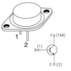
mj10023-40a-400v-npn-si-power-transistor-to-3-en-mj-mje-transistors-mos-54555-69-K.jpg


The metal case is the collector.. ie TAB
 
Last edited:
OK, I'll take those resistors out and check them, I did check them while on the board and they are close to 0.33ohms, but I should definitely check them for sure. To note, I attempted to probe for voltage readings, and in checking one of the positive leads to the filter cap, shorted it and almost certainly blew it up. Replacements are on the way. I will see if I can get proper readings for the output transistors at this stage. I believe I have the EBC ordering for the transistors correct, either way they aren't lining up properly.
TR701
E: 0V
B: 0V
C: +46V

TR702
E: +46V
B: 0V
C: +46V

TR703
E: -45.6V
B: 0V
C: 0V

TR704
E: -46V
B: 0V
C: 0V
 
Back
Top Bottom