• The move to the new server is done. There are some software and database maintenance updates in process. This has us passing the hat around to help out. We appreciate any donations. Seriously, even a dollar helps. The payment page may be found here - https://www.audiokarma.org/support.html

Stuck on a JVC JA-S55 DC overload problem

Corktowner

Active Member
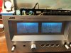
Hi all! I've gotten stuck and I need to reach out for some help. I am working on a JA-S55 which a friend of mine owns. He described the problem as scratchy, then a pop and then no sound. The unit looked like it had not been worked on previously except perhaps to change the light bulbs.

I started digging into the power circuit and I found that the center voltage on the LH channel was 33V (post 112-114 on the schematic). RH voltage was 70mV. So it seems there is a short somewhere in the LH circuit.

I checked the transistors first as there were only three. All tested fine on the diode check when removed from the circuit.

I started checking the resistors and I found three, R415, 419, and 420, which tested bad in the circuit but good when I pulled them out. So I assumed the short was related somehow to those.

However this is where I have hit my roadblock - the two most likely suspects I have from tracing the circuit ate either the Darlington Power Pack IC or the Protection circuit IC. Both seem readily available and inexpensive online, but I would like to confirm if they are bad if possible, or perhaps get pointed in the correct direction if I am wrong.

Any suggestions?

Thanks!!
 
Register to hide this ad
So if you are able to test the unit - and voltages - then you dont have a short - or are you testing with a DBT and the bulb is bright?
 
With +33Vdc at pins 113, 144, appears the protection circuit is doing its job.
Need to check the inputs to the chip, may be a case of bs-in bs-out. Measure
dc voltages at,
Pin 208/104
Pin 207/106
pin 205/105

Maybe compare with other side, ie,

Pin 204/103
Pin 202/101
Pin 203/102

Some of the voltages may be lower than the +33V, possible due to "feedback"

Don't know enough about the power packs to be of any real help...
 
Thanks for the help everyone, and sorry for not checking back in quickly. Life.

I replaced the power pack and all was working well for a little while. Now a new problem has come up. There is weakness in the left channel and also some distortion. Right channel is fine. DC offset for both channels is also fine, at < 10 mv. However the power meter for the left channel is holding steady at 0.1W after the protection relay clicks on. This did not occur immediately after the repair.

Has anyone seen this type of issue and perhaps can point me in the right direction?
 

Attachments

  • 2F3B7A27-C20F-4EAE-B0F4-ECCB68F2ECA6.jpeg
    2F3B7A27-C20F-4EAE-B0F4-ECCB68F2ECA6.jpeg
    75.4 KB · Views: 26
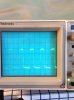
Hello again, time to resurrect this thread. I finally dug out my oscilloscope and learned how to use it (bought and calibrated many years ago and then never used). I found what I thought was the problem in transistors X301 and X311 in the LH channel. I changed them out with KSC2316KYA and KSA992FBTA, but I still have the problem.

The signal into X301 looks the same as into X302, but the output from X301 is very different. This effect carries on through the signal path and is amplified by X311 and X313.

I did find that the voltage at R301 is -0.11, spec is -0.03. The RH channel voltage at R302 is correct.

Does anyone have suggestions on how I can find the source (I.e. What to look at) for the over voltage?
 

Attachments

  • image.jpeg
    image.jpeg
    44.6 KB · Views: 12
  • image.jpeg
    image.jpeg
    48 KB · Views: 13
  • image.jpeg
    image.jpeg
    52.2 KB · Views: 12
  • image.jpeg
    image.jpeg
    50.1 KB · Views: 12
Any progress here? I have one with a couple issues too

I am still dealing with the DC overload issue on the LH channel. I’m measuring 1.65 V at the speaker terminal with no signal, so that’s tripping the protection relay. It’s been requiring me to (slowly) learn a lot about amplifier design, and right now I am focused on the JFET pair which make up the differential amplifier for the left channel. After I get a little bit better idea of how it is supposed to work I will take a few measurements. There is a very famous sticky on here about DC overload and it points to diff. amps as the usual culprit.

I am also learning about how to ensure the JFETs are matched for operation in the differential amplifier - I haven’t come across how to measure them yet to make sure.

What problem is yours having?
 
Back
Top Bottom