• The move to the new server is done. There are some software and database maintenance updates in process. This has us passing the hat around to help out. We appreciate any donations. Seriously, even a dollar helps. The payment page may be found here - https://www.audiokarma.org/support.html

Substitutes for uPA74 uPA75 double transistors

fox

New Member
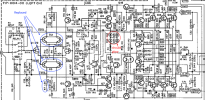
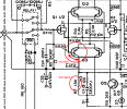
I recently acquired a Japanese amplifier with a dead channel. I tracked down the fault to a dual transistor uPA75. The base–collector junction is shorted, which in turn burned the R7 resistor. None of the other components seem to be affected.
1719445406510.png

I am looking for a good substitute for this dual transistor component. I was thinking that two modern transistors could work fine instead of trying to hunt down the hard-to-obtain part. However, I do not understand the role these transistors play in this circuit. In an old diyAudio thread, a member reported that they used a pair of BC546C and a pair of BC556C as substitutes. However, those transistors have a Vce of 65V whereas the uPA74/uPA75 have a Vce of 80V. That makes me think those transistors may not be good substitutes.

I have couple of questions:
1. Do you have any ideas for good substitutes for these transistors?
2. How important is that they're matched?
3. What is the role of these transistors?
4. Is the gain and the frequency important here?
5. If I replace the double transistor (uPA75) with the modern equivalents, is it a good idea to also replace its complementary pair?
 

Attachments

Last edited:
Register to hide this ad
The BCxxx transistors having a lower Vceo is a problem only if your particular circuit will exceed that voltage where the transistor is used. You've marked on the schematic where it shows -67v between those two legs, so you're right to question it.

The question, for me, is "does the datasheet value for Vceo for these BC5xx transistors represent the max the device will take? or a value they can actually exceed but aren't really rated for?" It's really close.

I would instead use a pairs of KSC1845 and KSA992 as they exceed with 120v/120v/5v/50mA and they are at least as good, noise-wise, as the BCxxx devices.
 
  • Like
Reactions: fox
Japanese amp - use KSC1845 and KSA992.
BC's are for American made gear.

I just used those subs in a Yamaha M-70 successfully.
 
  • Like
Reactions: fox
The BCxxx transistors having a lower Vceo is a problem only if your particular circuit will exceed that voltage where the transistor is used. You've marked on the schematic where it shows -67v between those two legs, so you're right to question it.

The question, for me, is "does the datasheet value for Vceo for these BC5xx transistors represent the max the device will take? or a value they can actually exceed but aren't really rated for?" It's really close.

I would instead use a pairs of KSC1845 and KSA992 as they exceed with 120v/120v/5v/50mA and they are at least as good, noise-wise, as the BCxxx devices.
Thank you!! :)

According to the datasheet of BC546 from Onsemi, the Vceo of 65V is their absolute maximum rating. In addition, the datasheet states that stresses exceeding those listed in the Maximum Ratings table may damage the device. If any of these limits are exceeded, device functionality should not be assumed, damage may occur and reliability may be affected.

So I assume they could probably work for a while under overload before becoming damaged.

Japanese amp - use KSC1845 and KSA992.
BC's are for American made gear.

I just used those subs in a Yamaha M-70 successfully.
Thank you for confirming that! :)

---

KSC1845 and KSA992 transistors look to be a good fit, and they're not expensive. Is matching of these devices in this circuit necessary? Would matching them just by hFE be sufficient?
 
Thank you!! :)

According to the datasheet of BC546 from Onsemi, the Vceo of 65V is their absolute maximum rating. In addition, the datasheet states that stresses exceeding those listed in the Maximum Ratings table may damage the device. If any of these limits are exceeded, device functionality should not be assumed, damage may occur and reliability may be affected.

So I assume they could probably work for a while under overload before becoming damaged.


Thank you for confirming that! :)

---

KSC1845 and KSA992 transistors look to be a good fit, and they're not expensive. Is matching of these devices in this circuit necessary? Would matching them just by hFE be sufficient?
hFE should be just fine.
 
  • Like
Reactions: fox
I replaced the transistors in the differential pair with closely matched pairs of KSC1845 and KSA992 and all electrolytic capacitors. However, the channel does not work as expected. Visually I observed that the LEDs D12, D13, D25, and D26 do not glow as they are supposed to (this was also observed when the fault occurred). However, when tested with a multimeter in diode mode, they measure fine and glow.

In addition, I have tested all other transistors and diodes against the working channel and the values are identical. That makes me question if there is a possibility that there is a half-working semiconductor somewhere?

Since the initial fault occurred in the input section (a shorted transistor in the differential pair), the fault is most likely contained in the input section?

Some of the measurements / tests I've done so far:
- The output devices measure fine,
- After replacing the differential pair transistors, there are no longer any shorts,
- The amplifier powers on and the relays click, and DC offset is < 1mV on the faulty channel,
- Voltage at the Test Point T.P. measures 0V (should measure about 88mV in class AB), so no current is reaching the output devices.

I am out of ideas at the moment. Does anyone have an idea what could be the problem or what could I test next to come closer to finding the fault?

1721774167509.png
 
Last edited:
I replaced the transistors in the differential pair with closely matched pairs of KSC1845 and KSA992 and all electrolytic capacitors. However, the channel does not work as expected. Visually I observed that the LEDs D12, D13, D25, and D26 do not glow as they are supposed to (this was also observed when the fault occurred). However, when tested with a multimeter in diode mode, they measure fine and glow.

In addition, I have tested all other transistors and diodes against the working channel and the values are identical. That makes me question if there is a possibility that there is a half-working semiconductor somewhere?

Since the initial fault occurred in the input section (a shorted transistor in the differential pair), the fault is most likely contained in the input section?

Some of the measurements / tests I've done so far:
- The output devices measure fine,
- After replacing the differential pair transistors, there are no longer any shorts,
- The amplifier powers on and the relays click, and DC offset is < 1mV on the faulty channel,
- Voltage at the Test Point T.P. measures 0V (should measure about 88mV in class AB), so no current is reaching the output devices.

I am out of ideas at the moment. Does anyone have an idea what could be the problem or what could I test next to come closer to finding the fault?

View attachment 3258506
Hi @fox,

Curious if you ever got your P-266 amp issue resolved?
 
Japanese amp - use KSC1845 and KSA992.
BC's are for American made gear.

I just used those subs in a Yamaha M-70 successfully.
Hi, Sorry to bother you. I have been strugling with M70. R ch DC offset jump around 0-450mV. Any idea? Will be really appreciated. Thanks
 
Back
Top Bottom