• Please note that Audiokarma will be offline briefly for updates early on Monday morning, September 28th.

Substituting Marantz 32 amplifier bias transistors sans data sheet

I believe ecluser has this right, in that it's better to seek thermal feedback from the driver transistors instead of the output devices when you're working with a CFP output circuit. What is your experience with bias drift after the suggested modification?

The service manual for the 32 does not include any bias voltages. Using a watt meter to set the bias level is the only method described. I have found this method to be vague at best. The two units I have worked on had initial settings of around 15 watts per channel.

Having CR203 and Q207 in contact with the heat sink are not modifications, it's the way they came from the factory. My understanding of this design is that the two components provide feedback based on the temperature of the heat sink to maintain the bias voltage.

I use a 32 often and I have found that the bias setting - in watts- seems stable even after long and high output use.

You have provided the only bias voltages I have seen for this model.
 
I've never worked (I mean physically) on this model but the heat sink you are talking about... is it for the power transistors (Q1 and Q2) or for the driver transistors (Q209 and Q210)? Usually the thermal sensistive components (diode, transistor) of the bias stage are thermally coupled to the power transistors in amplifiers. This is correct in most amplifiers but the topology of the model 32 dictates to favour a good thermal coupling to the driver transistors.

The heat sink is for the power transistors.
 
Sorry it took me so long to respond, I didn't get the email notifications for some reason. :dunno:

Unless I didn't read the schematic correctly. Can you confirm that R210=7.5k, R217=5.1k?

If my reading is correct and R215 is 56 Ohms, then the current in Q202 is approximately 0.1mA, and the current in Q201 is approximately 0.5mA. Since the tail current is 0.63mA, either transistors in the differential pair are at the edge of saturation.

Yes, I can confirm that R210 = 7.5k and R217 = 5.1k, both in the service manual and in the unit.

CR203 and Q207 are located on the back side of the amplifier PCB and should be in contact with the heat sink. On the units I have seen usually both components are not in contact with the heat sink. I add some thermal grease and readjust them so they make contact.

I actually removed the old thermal grease and added new grease on the power transistors and on CR203 and Q207 when I replaced the power transistors, and I can confirm that both are also making good contact with the heat sink.

There's good evidence now (from research) that bias current adjustment doesn't necessarily optimize crossover distortion performance. The theory is that one should rather adjust for 26mV across each emitter resistor, or 52mV across the pair. That would yield 130mA in the Marantz 32, which seems reasonable if it's stable. But these older amps do tend to drift quite a lot more than we're used to seeing in later designs. If you can improve bias drift by improving thermal coupling to the driver transistors, go for it. In general, bias drift is a fundamental weakness of class AB transistor power amplifier design.

I don't have any heatshrink or anything currently, so I don't know how well I can improve the thermal coupling with what I have, but I'll try to fashion something. I think I'll just use some electrical tape until I get home and have access to heatshrink (I'm away at college currently). The original driver transistors were heatshrinked together, actually, and the service manual does make a note of it. I never knew that amp bias depended this much on thermal characteristics, I'll be sure to let my amps warm up for quite some time before calibrating the biases now. :yes:

I believe ecluser has this right, in that it's better to seek thermal feedback from the driver transistors instead of the output devices when you're working with a CFP output circuit. What is your experience with bias drift after the suggested modification?

I'm very busy tonight, but I'll have time to set the bias to the suggested 52mV across resistors R230 and R231 tomorrow.

I would like to thank everyone for their help, assistance, and patience, I really do appreciate it. This is why I love AK! As a second-year EE major, I am also learning some little tidbits I haven't learned in classes yet. :thmbsp:
 
I also did some searching on Mouser, and I can't decide if the BD13910 or the MJE182 would be the best sub for the SS47 transistors. Based on the cross-referenced 2N2605 data sheet from post #3, it looks like the MJE182 might be a better choice, but neither look perfect.

The KSC2752O or KSC2752Y might be a potential sub for the S33690 as well. :scratch2:
 
I was re-reading parts of Bob Cordell's book last night, and it appears that the 52mV figure doesn't apply to CFP (complementary feedback pair) output stages. The correct figure is much lower. Do you have access to that book? Here's a link: http://www.amazon.com/Designing-Aud...=sr_1_1?ie=UTF8&s=books&qid=1303317125&sr=1-1

I don't think I have access to that book (i.e. I don't own it), it looks pretty good though. I do want to take a class on amplifier design at some point, maybe then I can read and understand it. 52mV did sound kind of high to me, I would think they should be biased at 20mV or less, but I'm not the expert here. :D
 
Just to follow up, I replaced the SS47 and SS48 transistors with MJE182 and MJE172 transistors, and they work perfectly. The amp sounds a lot better, too. I also replaced R215 with a 560 ohm resistor as suggested, and it seems that the popping sound has gone away. I haven't gotten replacements for the S33690 or S33691 transistors yet, but I'm glad that the SS47 and SS48 replacements were a success! Again, I would like to thank everyone for their help with this, you guys are fantastic. :tresbon:
 
Hello Guys,

I'm in the quest of restoring one model 32 as my first project and, till now,I found a lot of information for replacements. But im stucked with some parts.

Maybe ,as you have experience with this amp, you can give me a hand.

My amp its pretty bit up, specially the relay board, that has some missing parts (but I already have a lot of info that i found in internet on how to restore it) .

For the moment i cant find information for the replacements parts for Q209 (s33690) and Q210 (s33691), Maybe someone found a nice replacement for the two .

My knowledge in electronics is very limited, but im making what I can to make this amp work.

If you could help me with this or any information of this nice amp, i would be very thankful.

Sorry for my poor english!

Gonzalo
 
Hello Guys,

I'm in the quest of restoring one model 32 as my first project and, till now,I found a lot of information for replacements. But im stucked with some parts.

Maybe ,as you have experience with this amp, you can give me a hand.

My amp its pretty bit up, specially the relay board, that has some missing parts (but I already have a lot of info that i found in internet on how to restore it) .

For the moment i cant find information for the replacements parts for Q209 (s33690) and Q210 (s33691), Maybe someone found a nice replacement for the two .

My knowledge in electronics is very limited, but im making what I can to make this amp work.

If you could help me with this or any information of this nice amp, i would be very thankful.

Sorry for my poor english!

Gonzalo

I have never found a data sheet for Q209 (S33690) or Q210 (S33691). Are these 2 transistors actually bad in your amplifier?

The original transistors in the earliest model 32's were Q209 (SJE570) and Q210 (SJE569) perhaps these will offer some clues and a starting point when choosing a starting point for the later substitutes.

Here is a link to my rebuild of the relay/rectifier in a model 32.
 
I have never found a data sheet for Q209 (S33690) or Q210 (S33691). Are these 2 transistors actually bad in your amplifier?

The original transistors in the earliest model 32's were Q209 (SJE570) and Q210 (SJE569) perhaps these will offer some clues and a starting point when choosing a starting point for the later substitutes.

Here is a link to my rebuild of the relay/rectifier in a model 32.
Thanks for your help ChrisMarantz,

In fact in the left channel the Q210 was replaced with a TO-126 transistor; and the Q209, just has a yellow mark with now codes. So I suppose that are not the good matches (just guessing by the type of work done in this amp).Q208 and Q206 , are the original motorola, i didn't check them yet but i hope they are ok.

In the right channel Q210 was replaced by a Motorola replacement 2N4037 359 (but i have doubts if this isn't a fake motorola) , and Q209, has the same yellow mark as the left channel. Q207 and Q206 in this channel also the originals.

Thanks for the link, I already found it and archived it for reference when i go for the relay board. First i want to finish the L & R channels.

I dont know also if I'm going to change R231 and R230 because this are very low value resistors and I can't test them with my multimeter. They don't have visible marks of failure, but i saw already in internet two 32 restorations that have changed this resistors for new ones. Maybe its better to change them.

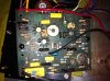
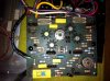
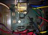
Im putting photos of the boards (i will try to put better photos tomorrow).

I have to repeat that my knowledge in electronics its very very basic, but in this research i'm learning little by little.

Thanks a lot for the help!
 

Attachments

  • Left channel board.jpg
    Left channel board.jpg
    85.3 KB · Views: 52
  • right channel board.jpg
    right channel board.jpg
    101.9 KB · Views: 45
  • Relay board.jpg
    Relay board.jpg
    97.8 KB · Views: 40
Hello

Your both channels has been "refixed" with strange components...Do you want to do the job at 100% by yourself ?

I think that the best way to act is to repair one channel (not the one with a screw used as heatsink ! ) and then you can use it as "reference"

I am sure that your relay is bad , one contact looks very damaged ...(high DC OFFSET ? )
On the "bad board " (the one in poor condition , there 2 cement resistors missing (maybe some other components not visibles on your picture )

A lot of job is waiting for you ...!
 
Hello

Your both channels has been "refixed" with strange components...Do you want to do the job at 100% by yourself ?

I think that the best way to act is to repair one channel (not the one with a screw used as heatsink ! ) and then you can use it as "reference"

I am sure that your relay is bad , one contact looks very damaged ...(high DC OFFSET ? )
On the "bad board " (the one in poor condition , there 2 cement resistors missing (maybe some other components not visibles on your picture )

A lot of job is waiting for you ...!
Hello Clinic audio.

Yes that was my idea, for sure its a big task for me, but i realy think that is no more harm that I can make to this amp.I own a model 250 and left it into a tecnitian here in paris, and he charge me like 80e for aligne it ( i think bias and offset) he didn't give me any documentation of this job (just a recive) and the right chanell now is runing really hot. He was suppose to be a good one but i realy doubt it, and he was not a really nice guy at all. He took 2 week more to give the amp to me back, and he told me that , he had to ask for a replacement to Uk. I went to my house opend the amp and realized that he didnt change anything in it.

Well , now mi goal is to check all the parts that i can check with the multimeter, and replece the dameged ones with replacements just looking what other people has done, then cross my fingers and light it up, if this works, then try to aligne the dc offset an bias my self (for first time), sounds to crazy?

It doesnt have to many parts , so i think its a good divice to learn.

Thx a lot!
 
Just to follow up, I replaced the SS47 and SS48 transistors with MJE182 and MJE172 transistors, and they work perfectly. The amp sounds a lot better, too. I also replaced R215 with a 560 ohm resistor as suggested, and it seems that the popping sound has gone away. I haven't gotten replacements for the S33690 or S33691 transistors yet, but I'm glad that the SS47 and SS48 replacements were a success! Again, I would like to thank everyone for their help with this, you guys are fantastic. :tresbon:

Just to update this thread based on some PMs I have received recently, I did find substitutes for the S33690 (NPN) and S33691 (PNP) transistors, but due to a surprising lack of documentation on my part, I am only certain that they were TO-220 devices manufactured by ST Microelectronics. I only know this due to some pictures I took when I was selling the unit, which is since long sold. I am almost certain they were MJE3055 (NPN)/MJE2955 (PNP) devices based on a Mouser order about 3 weeks after my last post in this thread and the hfe values listed in the OP, but there is a tiny chance they were TIP31C (NPN)/TIP32C (PNP) devices as well. Whatever they were, they worked perfectly in my amp until I sold it. I feel very confident recommending the MJE3055/MJE2955 devices for substitution, but substitute at your own risk!
 
I see this is an old thread, but just wanted to state for the record that I was more successful with 2N5680/2N5682 than MJE182 and MJE172 to replace SS47 and SS48. Not sure why my 32 didn't like the MJEs.

The 2N have higher voltage ratings, but lower fT. They look much better on the board!
 
Last edited:
Back
Top Bottom