abnormalcat
New Member
Howdy all,
After being down for maintenance for nearly a year, I've finally finished replacing all the electrolytic caps in my Heathkit AA-1640. I got it off Facebook Marketplace from a guy who had it sitting in his closet for a few decades, and it worked quite nicely, but better to be cautious and all that, than have to figure out why something died later.
If you just want to look at pictures, they are attached. If you want to read my ramblings first and then look at pictures, you have been warned.
I learned a few things along the way. How useful flux is for getting good solder joints. How to use a multimeter to get the reading you need. How to drain giant capacitors without sparks or electrocution. How to order part from Mouser and similar websites. Overall this amp was incredibly easy to work in. You'll find it easy to work in too, unless you're trying to take the amplifier boards out, in which case, good luck. There are 13 (or 14?) things attached to the heat sinks on both channels. The "pre-amplifier" board was also a royal pain to get to, but such is life.
I bought a recap kit from HiFi Audio. It had a bunch of film caps that I didn't replace, and was missing the electrolytics for the preamplifier board, the nonpolar caps on the amp boards, and I think another pair somewhere. It was nice as a beginner, but going forward I'll probably just buy all my own parts. The inclusion of fuses and replacement bulbs for the front was a big bonus, however.
Work done: Replaced all electrolytic capacitors. Replaced a crispy-looking resistor and it's matching part on the other channel. Calibrated the front gauges. Used deoxit on the gain pots (thanks dad). Replaced the output jacks with binding posts.
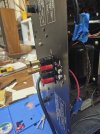
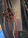
A bit about the binding posts. I had originally bought some really nice, big binding posts and planned to drill through the back panel. In planning those holes, I ran into spacing issues. As roomy as the amp is inside, there isn't a metric ton of space in the back to drill holes without impacting the outer text, the inner sticker from the factory (a factory-built heathkit!), or any number of other things. Instead, I had a friend design a 3d printed part to put in the existing output slot and got the part printed for $0.40 at the library. I had to shave down some of the plastic washers on the binding posts I used, and ream out two of the holes on the part. The jacks are also not spaced anywhere close to standard spacing. But, I didn't have to modify the chassis in any way which is a win in my book.
Big shoutout to my dad and my brother for helping me problem-solve as I ran into things. And thanks to all y'all who gave me advice when I asked on here.
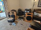
In terms of sound, I can't say, given as I have very few reference points, except it sounds very good and is a joy to use. Between the looks, the sound and the how it makes all the lights flicker when it turns on like in some mad scientist's lab, if you can get your hands on one of these 60lb beauties (for a reasonable price), do it.
(pre work)

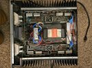
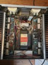
(the inside, before any work)
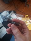
(this gloriously oversized resistor drained the massive filter caps)
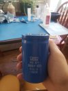
(The new filter caps, feat maple syrup in the back)
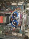
(installing the new caps very easy. I used a lot of tape with sharpie lables to keep everything organized)
(power supply board pre and midway through. Not the cleanest job, but I was completely new at it so cut me some slack)
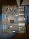
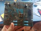
(Found a crispy-looking cap on one amp board. It was actually crisped by the neighboring resistor)
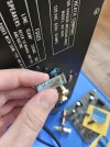
(this "pre-amplifier" board is sandwitched between the man "tub" of the chassis and the front plate with the gauges. it's held in by two screws with nuts and lock washers. I had to de-solder the wires as I worked it out, as there wasn't a lot of slack in the system. This was by far the most challenging piece to take out and put back in.)
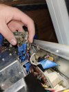
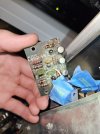
(another look at that "pre-amplifier" board. To my best guess, it creates a perfect source for the amp boards)
Oops I hit the attached file limit, I'll wrap this up in a comment if I'm able. Have a good one all!
After being down for maintenance for nearly a year, I've finally finished replacing all the electrolytic caps in my Heathkit AA-1640. I got it off Facebook Marketplace from a guy who had it sitting in his closet for a few decades, and it worked quite nicely, but better to be cautious and all that, than have to figure out why something died later.
If you just want to look at pictures, they are attached. If you want to read my ramblings first and then look at pictures, you have been warned.
I learned a few things along the way. How useful flux is for getting good solder joints. How to use a multimeter to get the reading you need. How to drain giant capacitors without sparks or electrocution. How to order part from Mouser and similar websites. Overall this amp was incredibly easy to work in. You'll find it easy to work in too, unless you're trying to take the amplifier boards out, in which case, good luck. There are 13 (or 14?) things attached to the heat sinks on both channels. The "pre-amplifier" board was also a royal pain to get to, but such is life.
I bought a recap kit from HiFi Audio. It had a bunch of film caps that I didn't replace, and was missing the electrolytics for the preamplifier board, the nonpolar caps on the amp boards, and I think another pair somewhere. It was nice as a beginner, but going forward I'll probably just buy all my own parts. The inclusion of fuses and replacement bulbs for the front was a big bonus, however.
Work done: Replaced all electrolytic capacitors. Replaced a crispy-looking resistor and it's matching part on the other channel. Calibrated the front gauges. Used deoxit on the gain pots (thanks dad). Replaced the output jacks with binding posts.
A bit about the binding posts. I had originally bought some really nice, big binding posts and planned to drill through the back panel. In planning those holes, I ran into spacing issues. As roomy as the amp is inside, there isn't a metric ton of space in the back to drill holes without impacting the outer text, the inner sticker from the factory (a factory-built heathkit!), or any number of other things. Instead, I had a friend design a 3d printed part to put in the existing output slot and got the part printed for $0.40 at the library. I had to shave down some of the plastic washers on the binding posts I used, and ream out two of the holes on the part. The jacks are also not spaced anywhere close to standard spacing. But, I didn't have to modify the chassis in any way which is a win in my book.
Big shoutout to my dad and my brother for helping me problem-solve as I ran into things. And thanks to all y'all who gave me advice when I asked on here.
In terms of sound, I can't say, given as I have very few reference points, except it sounds very good and is a joy to use. Between the looks, the sound and the how it makes all the lights flicker when it turns on like in some mad scientist's lab, if you can get your hands on one of these 60lb beauties (for a reasonable price), do it.
(pre work)
(the inside, before any work)
(this gloriously oversized resistor drained the massive filter caps)
(The new filter caps, feat maple syrup in the back)
(installing the new caps very easy. I used a lot of tape with sharpie lables to keep everything organized)
(power supply board pre and midway through. Not the cleanest job, but I was completely new at it so cut me some slack)
(Found a crispy-looking cap on one amp board. It was actually crisped by the neighboring resistor)
(this "pre-amplifier" board is sandwitched between the man "tub" of the chassis and the front plate with the gauges. it's held in by two screws with nuts and lock washers. I had to de-solder the wires as I worked it out, as there wasn't a lot of slack in the system. This was by far the most challenging piece to take out and put back in.)
(another look at that "pre-amplifier" board. To my best guess, it creates a perfect source for the amp boards)
Oops I hit the attached file limit, I'll wrap this up in a comment if I'm able. Have a good one all!