• The move to the new server is done. There are some software and database maintenance updates in process. This has us passing the hat around to help out. We appreciate any donations. Seriously, even a dollar helps. The payment page may be found here - https://www.audiokarma.org/support.html

Suggestions for unknown capacitors

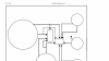
If you look up a few replies I have it written out as well. 2 wires coming from each. Some go to both capacitors, some to only one. It is an odd setup for sure. In the diagram the 2 rectangles are the capacitors.
 
Yes, 5 speakers and they are all connected to either one or both of the capacitors. Odd set up for sure . Caps are relatively cheap so I could just buy a range and see what sounds best. What would be a good starting point to get in the ballpark? The one speaker that is still hooked up has dried out paper caps and it still sound decent so I am thinking and cap in a safe range will get good results.
 
Well -- in the absence of any other data on these speakers... what I would probably do is borrow (or buy) a decent "LCR" meter to measure the actual capacitance of each XO capacitor.

Now -- each of the two capacitors in the "good" speaker crossover only has two leads (wires) sticking out of it, yes? I ask because (especially in the 1960s) it wasn't uncommon to find dual capacitors in one package used for speaker crossovers (KLH comes to mind). A dual capacitor would probably have three leads, and maybe even four.

Take plenty of photographs to be 100% sure that you know how the original crossovers were wired, then snip out one capacitor and measure its actual capacitance with the meter. Use the leads provided with the meter or use test leads as short as possible. Chances are the "actual" capacitance of each capacitor is still within a factor of 2 or so of the intended value.

Do that for each of the two capacitors and then order a selection of capacitors "around" the actual values. E.g., suppose you measure one to be 5 uF. Order, say, a 2 uF, a 5 uF and a 10 uF.

IF the crossovers are first order (and, given what "we" know right now, that's not a given) the crossover frequency, fc, is given by this equation:

fc = 1 / (2 * pi * R * C)

where pi = 3.14159265... (good old π)
R = the load (speaker driver) impedance
C = the capacitor value (in Farads -- one Farad = 1,000,000 uF)

This is the equation used by the crossover calculators.
From this equation, and for a 8 ohm speaker driver (R = 8), we can see a 1 uF capacitor corresponds to fc = 20,000 Hz, for example.
Similarly:

C = 2 uF corresponds to fc = 10,000 Hz
C = 5 uF corresponds to fc = 4,000 Hz
C = 10 uF corresponds to fc = 2,000 Hz
C = 20 uF corresponds to fc = 1,000 Hz

etc.

My suggestion: If you go this route, buy a bunch of cheap nonpolarized electrolytics for your experiments.
If you find values you like, and if you really like the loudspeakers, then go back and invest in better quality XO capacitors at the values you chose.


:)

I've gotta say I am baffled by these speakers :(
You might want to ask about them at a site such as DIY HiFi...(?)

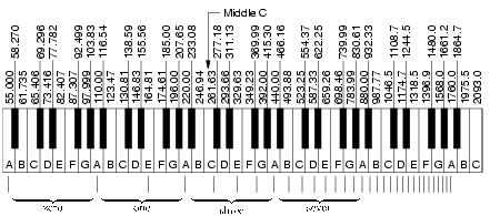
To put these crossover numbers into perspective, here's how the notes on a piano keyboard correlate to fundamental frequencies.

frequencies.jpg


Awesome reply. Thank you. That gives me a direction to go in. Do you think the caps still will give any useable measurement? When I took them out of the first speaker they just crumbled like dust. There is a family owed electronics store here so I will see if they sell LCR meters before I order one. They have a HUGE selection of caps too so maybe they have what I need
 
What I would do, were it me:

Document the current wiring very carefully & thoroughly then snip the leads to one capacitor "in situ" (leave the capacitor right where it is). Leave enough of the leads to hook the meter on to later.
Then measure.

After the whole process is finished, do the same to the other capacitor.

If anything goes terribly wrong, I'd think -- hard -- about simply re-designing the XO in a sensible way given four drivers (two of which are identical).

Here's what PartsExpress has for LCR meters - I cannot vouch for any of them, though.
See what you can get locally; couldn't hurt.

https://www.parts-express.com/cat/lc-lcr-meters/540
 
Ok, let the confusion continue. Picked up a LCR meter. Cut and tested the larger cap first. 36pf. Smaller cap comes up as a 1 ohm resistor. Huh? So then I tested the cap I had removed from the other speaker. Larger one was 336 pf (and not 36pf like the other one but about a 3rd of it is gone, crumbled off when removing it so I don't trust the reading) and the smaller tested the same, 1 ohm resistor. I have lots of new caps and resistors for antique radios (1920s-40s) so I tested those to verify the meter and they were all perfect. Could the smaller actually be a resistor? They are identical style (phone book style) and have the wires mounted the exact same way on the foil wrapping.
 
whats known as a capistor ... otherwise known as an ex capacitor . its dead as can be .
is there not any visible writing on the outside layer ?
 
Nothing, looks like a brown paper bag. Might have originally been on the bottom side but since it is half submerged in black silicon goop the paper just tears off when removing the caps. The two I have out only have the inner foil wrapping now.
 
not much to go on then . it is looking like experiment time with close candidates as already suggested .good luck .hope you sort it . i know it would take me a long time .
 
Back
Top Bottom