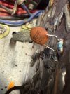
Post from Skippy124, Jan 2011, in FAQ sticky of Exclusively Sansui forum.
http://www.audiokarma.org/forums/showpost.php?p=4347793&postcount=55
Hi,
I recently acquired a 5000, and was intent on performing the modifications as shown at the start of this thread, but ran into some problems.
The reason for this post is twofold, the alternative bias diodes NTE-605a and STV-2h are not available locally, and from what I can gather are almost impossible to get hold of anywhere, so I needed an alternative for these. The second reason for the post is that the fault on the 5000 I have was left channel distortion, which turned out to be a corroded base lead on the 2SA485 bias transistor, and I am having difficulty finding a suitable alternative for the 2SA485/2SC485 pair in a metal can case.
Inspired by the excellent work EchoWars has done in identifying alternative bias diodes I decided to use 2 1N4148 diodes in place of the old LV-2 diodes.
In searching for alternative transistors, I settled on the commonly available BD139/BD140 complementary pairs, the specs are a reasonable match to the originals.
Last was to work out a way of making a transistor/bias diode assembly that would provide the thermal equivalent of the old assembly, and the following details what I did.
This is a modification instruction that will replace the old 2SA485/2SC485 bias assemblies with new assemblies made from readily available components
What you will need
BD139 x2
BD140 x2
1N4148 x8
1.5mm (or 1/16") dia heatshrink, approx 35mm length (1 1/2")
6mm dia (or 1/4") heatshrink, approx 50mm length (2")
Suitable hookup wire, 2 colours, approx 100mm (4")
Also, before starting any work on the unit, take out the protection fuses on the rear panel and discharge the power supply and output caps as per the instruction in the first post in this thread.
A new assembly is made up from one transistor and a diode pair in series. I chose to connect one end of each diode pair directly to the base of each transistor, as this is the way they end up being connected when assembled to the PCB, You could do it with two leads for the diode pair if you wish.
This is what we want to end up with for pair of assemblies
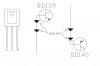
Start by first pre-bending the transistor leads to match the hole layout in the PCB. The holes in the PCB are tight, and correct alignment will make fitting easier….
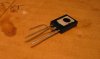
…and then make up a transistor/diode pairs like this (this shows the BD140 PNP transistor, the BD139 NPN is the same except the diode pair are reversed). NOTE: as these components are being soldered very close to the body of the component, use care with the soldering, only apply heat for as short a time as possible to make a joint. Also take care with the termination of the diode to the base lead of the transistor - make sure that it is not shorted to the adjacent collector lead.
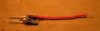
The assembly is then covered with the larger heatshrink (approx 1/2" length). The 6mm dia heatshrink is a tad undersized for this, I stretched it just a little using long nose pliers prior to fitting. I used two different colour flying leads to easily distinguish between the BD139 and BD140 as the component coding is covered by the outer heatshrink.

Assuming that the old assemblies have been removed for the PCBs, the new assemblies can now be fitted. Make sure that the holes in the PCB are clear, as the new transistor leads are a tight fit. The diode leads are fitted as follows:

And

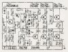
And this shows the new assemblies fitted
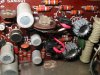
The bias pots should be wound fully CCW prior to turn on, and then bias set as per the service manual (23ma measured at the protection fuse for each channel).
Notes:
- Remember to replace the protection fuses on the rear panel.
- I did this without removing the boards as I didn't have a high wattage soldering to desolder the braid earth connections. I did remove the RHS capacitors to get access to the component side of the RHS PCA. It would be easier if the boards were removed, and care should be taken when removing the old bias assemblies, the pads on the board are a little fragile.
- the diodes could be assembled using two flying leads as per the original arrangement if so desired.
- These instructions are for the F1040 PCA, and I assume that they will also be applicable to the later F1040-1 PCA.
And a final word of advice to owners of 5000's and 5000A's with F1040 and F1040-1 PCA's. As stated earlier in this post, the failure in my 5000 occurred due to the base lead on one of the 2SA485's corroding off the body of the transistor. All of the 2SA485/2SC485's I removed had evidence of corrosion on the leads (and the interior of my 5000 had no other signs of corrosion. lead oxidation etc)

They would have all failed sometime in the future.... a time bomb waiting to go off. I would suggest that you have a look next time you have the covers off, it is relatively easy to see if there is corrosion present.
My original thread on this is here
http://www.audiokarma.org/forums/showthread.php?t=347022
I hope this is of some use to other 5000 owners in the future. If anything is not clear or if anyone has and questions either PM me or post up here.
Cheers
John
(Mod edit: Thanks to ghazzer for the restoration. )
http://www.audiokarma.org/forums/showpost.php?p=4347793&postcount=55
Hi,
I recently acquired a 5000, and was intent on performing the modifications as shown at the start of this thread, but ran into some problems.
The reason for this post is twofold, the alternative bias diodes NTE-605a and STV-2h are not available locally, and from what I can gather are almost impossible to get hold of anywhere, so I needed an alternative for these. The second reason for the post is that the fault on the 5000 I have was left channel distortion, which turned out to be a corroded base lead on the 2SA485 bias transistor, and I am having difficulty finding a suitable alternative for the 2SA485/2SC485 pair in a metal can case.
Inspired by the excellent work EchoWars has done in identifying alternative bias diodes I decided to use 2 1N4148 diodes in place of the old LV-2 diodes.
In searching for alternative transistors, I settled on the commonly available BD139/BD140 complementary pairs, the specs are a reasonable match to the originals.
Last was to work out a way of making a transistor/bias diode assembly that would provide the thermal equivalent of the old assembly, and the following details what I did.
This is a modification instruction that will replace the old 2SA485/2SC485 bias assemblies with new assemblies made from readily available components
What you will need
BD139 x2
BD140 x2
1N4148 x8
1.5mm (or 1/16") dia heatshrink, approx 35mm length (1 1/2")
6mm dia (or 1/4") heatshrink, approx 50mm length (2")
Suitable hookup wire, 2 colours, approx 100mm (4")
Also, before starting any work on the unit, take out the protection fuses on the rear panel and discharge the power supply and output caps as per the instruction in the first post in this thread.
A new assembly is made up from one transistor and a diode pair in series. I chose to connect one end of each diode pair directly to the base of each transistor, as this is the way they end up being connected when assembled to the PCB, You could do it with two leads for the diode pair if you wish.
This is what we want to end up with for pair of assemblies
Start by first pre-bending the transistor leads to match the hole layout in the PCB. The holes in the PCB are tight, and correct alignment will make fitting easier….
…and then make up a transistor/diode pairs like this (this shows the BD140 PNP transistor, the BD139 NPN is the same except the diode pair are reversed). NOTE: as these components are being soldered very close to the body of the component, use care with the soldering, only apply heat for as short a time as possible to make a joint. Also take care with the termination of the diode to the base lead of the transistor - make sure that it is not shorted to the adjacent collector lead.
The assembly is then covered with the larger heatshrink (approx 1/2" length). The 6mm dia heatshrink is a tad undersized for this, I stretched it just a little using long nose pliers prior to fitting. I used two different colour flying leads to easily distinguish between the BD139 and BD140 as the component coding is covered by the outer heatshrink.
Assuming that the old assemblies have been removed for the PCBs, the new assemblies can now be fitted. Make sure that the holes in the PCB are clear, as the new transistor leads are a tight fit. The diode leads are fitted as follows:
And
And this shows the new assemblies fitted
The bias pots should be wound fully CCW prior to turn on, and then bias set as per the service manual (23ma measured at the protection fuse for each channel).
Notes:
- Remember to replace the protection fuses on the rear panel.
- I did this without removing the boards as I didn't have a high wattage soldering to desolder the braid earth connections. I did remove the RHS capacitors to get access to the component side of the RHS PCA. It would be easier if the boards were removed, and care should be taken when removing the old bias assemblies, the pads on the board are a little fragile.
- the diodes could be assembled using two flying leads as per the original arrangement if so desired.
- These instructions are for the F1040 PCA, and I assume that they will also be applicable to the later F1040-1 PCA.
And a final word of advice to owners of 5000's and 5000A's with F1040 and F1040-1 PCA's. As stated earlier in this post, the failure in my 5000 occurred due to the base lead on one of the 2SA485's corroding off the body of the transistor. All of the 2SA485/2SC485's I removed had evidence of corrosion on the leads (and the interior of my 5000 had no other signs of corrosion. lead oxidation etc)
They would have all failed sometime in the future.... a time bomb waiting to go off. I would suggest that you have a look next time you have the covers off, it is relatively easy to see if there is corrosion present.
My original thread on this is here
http://www.audiokarma.org/forums/showthread.php?t=347022
I hope this is of some use to other 5000 owners in the future. If anything is not clear or if anyone has and questions either PM me or post up here.
Cheers
John
(Mod edit: Thanks to ghazzer for the restoration. )
Last edited by a moderator: