• The move to the new server is done. There are some software and database maintenance updates in process. This has us passing the hat around to help out. We appreciate any donations. Seriously, even a dollar helps. The payment page may be found here - https://www.audiokarma.org/support.html

Surface mount soldering repair help needed.

rkgren1

Super Member
I have a Weller EC2000 soldering station which has begun to misbehave. I opened the unit up and the switch shown on the left (back side visible) fell out.

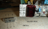
The switch swaps the display between set point and actual temperature. Obviously it has broken from its solder pads. It is a surface mount attachment. See the picture below with switch and solder pads labeled.

Note the locations of the long contacts 4,5,and 6, and that the switch sits hard up against the LED display, so access with a soldering iron is not possible for pads 4,5, and 6.

Any hints from experienced techs out there about how I can resolder this in place?
 

Attachments

  • SWITCH.png
    SWITCH.png
    619.1 KB · Views: 77
Register to hide this ad
I'd solder wire strands to pins 4,5,6, kind of "C" or "L" shape, so you can flip the switch a bit, then solder 1,2,3 from the outer edge if possible.

There is a low melting point solder that stays melt for 10-15 seconds, but I'm not sure if you can heat all 6 points and work that fast.
 
I think the proper way to do this is to clean the pads, apply solder paste, plant the switch in the paste, and then apply heat with a hot air gun on the opposite side of the board. You might be successful with three solder blobs and liquid flux just for the three switch terminals, then hand-soldering on the frame. No-clean flux would be best.
 
If you had to a different type of switch it could be mounted and the wires soldered to 4,5,6. The slide switch just shorts 5 to either 4 or 6 depending on reading set or actual temp.
 
Thank you for the replies, all.

I will obtain some soldering paste and try that approach.
I need to order a few electronic bits and pieces for other projects anyway.

I can reach 1,2,3 with a soldering iron.

Worst case scenario is simply soldering in a jumper to display current temperature and mark those temperatures on the dial.

Thanks again.
 
1, 2 and 3 are not connected. I would bridge 1-4, 2-5 and 3-6, then flip the switch upside down so that you can solder the contacts to 1, 2 and 3. Original functionality restored!
 
1, 2 and 3 are not connected. I would bridge 1-4, 2-5 and 3-6, then flip the switch upside down so that you can solder the contacts to 1, 2 and 3. Original functionality restored!

How do you know there aren't through plated connections to the other side of the PCB for 1, 2, and 3 ?

I think you should be able to solder all but pin 5 - to connect that pin you can solder some tinned copper wire to pin 5 on the switch, form it, and then position it, solder the 5 pins, and then solder the tinned copper wire to the track connecting to pin 5.

You would need a soldering iron with a small bit, and when soldering pins 4 & 6 flip the switch so that the contacts don't suck heat out of pin 4 and pin 6 respectively when soldering.
 
Last edited:
Is the LED display surface mount or through hole? If it's through hole, I'd unsolder and remove the display, install the switch then re-install the display.
 
How do you know there aren't through plated connections to the other side of the PCB for 1, 2, and 3 ?

I think you should be able to solder all but pin 5 - to connect that pin you can solder some tinned copper wire to pin 5 on the switch, form it, and then position it, solder the 5 pins, and then solder the tinned copper wire to the track connecting to pin 5.

You would need a soldering iron with a small bit, and when soldering pins 4 & 6 flip the switch so that the contacts don't suck heat out of pin 4 and pin 6 respectively when soldering.
It's a single sided board. Caveman-level sophistication. They are not vias, they are pads. Not connected on the other side.
 
i bet the switch was soldered to the board first . the display may or may not be in the way .. you could try masking it off so the hot air doesn't damage it whilst soldering the switch back on .
p.s get the switch back on the right way round as it only has contacts one side .
 
Do it right. Remove the display and then you can properly solder the switch. Then put some epoxy under the switch to support it. This is poor design. A switch that is used all the time and takes some force to operate should not be surface mount, it should have been a thru hole switch.
 
edge-connect.jpg

Thanks again for all of the help so far.

Zoom is correct. There are 2 single-sided boards, bonded together with foam spacers. There are soldered connections between them adjacent to the ribbon cable. I definitely do not want to desolder the LED. It has lots of contacts on it and they are beneath it where I cannot see them easily. My skills in this sort of thing are limited.

I had decided to try to resolder the switch with solder paste. I have only a paint-stripper type of heat gun available to me, which will not give me much control over how much heat I apply or where I apply it.
I do however have a toaster oven.

What do you all think of the idea of heating a metal block to temperature, pulling it from the oven onto an insulating surface, and using it as the heat source under the switch?

I agree with dr*audio's assessment of poor design. The switch has holes for fasteners. Someone in Weller's product design department was squeezing an extra nickel out of the design by omitting fasteners. It did last 20 years or so, though. So I should not complain too loudly. Prior to reassembly I will drill the housing adjacent to the switch hole so that I can use a couple of small machine screws to hold it in place. I will just need to apply new labels over the screws.
 
The board was probably soldered at the factory with what amounts to a hot plate, so the metal block idea may not be far off the mark. If solder paste is hard to get, you might try wrapping flux-core wire solder around the switch terminals instead. Just make sure there's enough clearance so the resulting solder blobs don't short. Keep in mind that every existing solder joint will liquify again when you do this, and don't disturb things until they're cool. The factory soldering machine has a belt that carries hot boards gently into a cooling zone after a closely regulated heating cycle.
 
i thought of 2 more ways to fix it ..one is get a through hole mounted switch and drill the board and insert pass through .. might not need them but solder may wick through better ..
another way is cut the board where the switch sits .. solder wires from switch to board .
 
If you are installing it with screws, I'd use small wire strands. Easier. If you can drill the board (I don't know what is at the back), that's a good solution too...
 
The metal plate will not work. If the display is surface mount then the only way to resolder the switch is with a reflow oven. You can do it in a toaster oven. We used to to it that way at work until we got a real reflow oven. They cost $800. The problem with a toaster oven is they don't have good enough temperature control. They go too hot and can damage components. I am worried about melting the LED. I think the best way to fix this would be to solder short wires onto the switch and then solder them to the board, then epoxy the switch to the board.
 
Thanks to all for the help.
After pondering the chance that I would damage the LED, I decided to implement a fix that minimized my risk of going wrong.

I found the closest mount point for the switch that made sense, and I cut holes for the switch and screw holes. Webs inside the case drove the choice of locations to the shelf area below the dial.

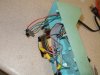
I wired the switch to the pads on the board.

I still need to get a couple of proper flat head screws and nuts to hold the switch in place.
The pic below show me holding the switch in place over the too-short screws.
The picture gives the impression that the LED is not there. That's just a reflection.

I test ran the thing and it now works great.

The bar at the top of the "8" on the left-had LED is now out.

I will settle for that.

P8150003.jpg P8150004.jpg
 
Last edited:
Back
Top Bottom