• The move to the new server is done. There are some software and database maintenance updates in process. This has us passing the hat around to help out. We appreciate any donations. Seriously, even a dollar helps. The payment page may be found here - https://www.audiokarma.org/support.html

Switching Marantz 1040 from 220V to 110V

ThreeMartinu

New Member
Hi - Longtime reader here, finally registered.

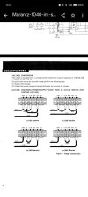
I recently bought a Marantz 1040 that was totally recapped and even has a (only slightly janky) custom-built wood case. But it's wired for 220v and I'm in the U.S.

I see in the manual that it's a very simple process to rewire the voltage to 110 but I have a couple questions:

1) What kind of cables are those switchable ones? I'm going to need one or two additional but I don't even know what they're called. The closest results I can find online quickly diverge into sites selling car stereo jumper wires instead.

2) I'll have to also switch the fuse, yes? But which fuse, and to what amperage?

3) Maybe this doesn't matter but in discussions about power supply there is frequently talk about bias offset adjustment. I don't really know what that is. Will I need to address it because changing the voltage setup?

Thanks in advance for any help!

- Gabriel
1000115428.jpg
 
Register to hide this ad
3) Maybe this doesn't matter but in discussions about power supply there is frequently talk about bias offset adjustment. I don't really know what that is. Will I need to address it because changing the voltage setup?
In theory no, since you are only chaning the primary supply, the secondary voltages "should" remain the same. However in practice there probably will be a very small change in secondary voltages so this would trigger a check of bias and offset.

For each channel you need to check the dc offset, residual dc voltage at speaker terminals, ideally 0mV, stable and under +/-10mV is great. Also need to measure the bias current, the idle current flowing through the output transistors. Refer to page 2 of the sm "Power Amplifier Adjustments"
 
Thank you so much for the help! Setting aside the bias for now, I'm trying to be sure which fuses need to be changed to what.

The only fuses I see in the manual's parts list are on page 18, where it lists F001 as "3A 250V for USA" which seems clear,
and on page 17 where it says F701 and F702 should be "3.5A 250V" without any USA specification.

At the very end of the manual on page 26 it also lists an F002 as "250V 2A," and F003 and F004 as "250V 1A"
but these are shown right next to the voltage conversion instructions and they have an asterisk underneath that says "To be used in the European Model Only." (BUT there is no corresponding asterisk anywhere above that note, so maybe it applies to the whole parts list on page 26?)

Most photos of the inside show 4 fuses all in a row, so I don't know which are supposed to be which.

Thanks again!
 
You only need to change fuses on the primary side. The secondary voltages will remain the same so the fuses remain applicable.
F001 as "3A 250V for USA" which seems clear
yep, change due to change in primary windings

on page 17 where it says F701 and F702 should be "3.5A 250V" without any USA specification.
These are speaker protection fuses, power amp output, audio path not mains AC. Don't change

maybe it applies to the whole parts list on page 26?
Agree that it's not very clear, yes probably those are the part values for the EU model.
Again, only need to change fuse on primary side.
 
This is great. I really can't thank you enough!

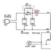
One last question: Where the heck is F001? Looking at the schematic it might be between the plug and the transformer, maybe tucked down under the jumper wires?
1000115552.jpg
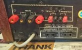
Or, my unit just has a little cap where some have a removable fuse holder. So possibly F001 is right on the other side of it inside?

13ddfa16-c1ae-454c-9bd4-7ef8a081627a.jpeg
 
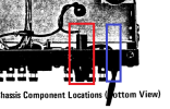
Yeah that power cord routing does not appear OEM, the capped hole to the left is for the power cord and the other is for the fuse holder, if you inspect closely you will see that its tapped/threaded. See pix from sm showing bottome view.

You will need to trace the wires from the power cord, there should/must be an inline fuse.
 

Attachments

  • 1040.png
    1040.png
    48.3 KB · Views: 6
Back
Top Bottom