


Good Evening from Ohio!
Been working on restoring this beautiful receiver for some time now and I've replaced all caps and transistors except for the tuner boards, and the 4 main output transistors. The 4 big filter caps have been replaced, installed new 7 0.68 wirewound cement resistors on the bottom that have been recommended to swap out, and also replaced the diodes on the power supply. My dc offset is at steady -14 mv for both left and right channel, and on the main amp W15-027 i'm getting 75.2v for pin 6 on both left and right channel, and pin 3 is at 39.3v for both left and right.
But, when I turn the balance pot to the right channel the right channel cuts out, also when switching the low filter on and off I get a loud pop and when switching the high filter on and off I still get a pop but not as loud. This occurs no matter what the receiver is set too, fm, am, aux, etc, currently it's on aux, vol down to zero, bass and treble set to middle.
I know enough to know that I don't know anything but I do have a fluke multimeter, dim bulb tester, variac, scope tektronics 2235, and a signal generator leader lag 120a. I’m still super new to electronics and I bought the scope awhile ago with hopes of learning how to use it properly, I’ve read the manual and have learned how to set a baseline, but beyond that I haven’t had much experience, so this looks like the perfect time!
Yesterday after reading other threads on audiokarma and some youtube videos I was able to run a 1k signal through the aux input on the receiver and was able to pick up a signal using the scope. I started at the Vol and did get a clean signal, then at the balance knob the signal was jittery on the right but clean on the left but I’m not sure if that’s because of the probe I’m using (It’s a cheap knockoff) or the scope.
On the control amp W15-031 at pin 10 for the right channel which according to the schematics for W15-031 is the input I was able to get a clean wave and at pin 2 which is output for the right channel the signal is very jittery, as in there are two waves and they keep crossing each other, I hope I’m making sense.
I tried following the schematics and working back from Pin 2 and comparing it to the working channel but it’s still very confusing, but I feel that I was able to find that the signal comes back clean after C622 which is 1uf 10v. I’ve tested the following by lifting one leg from the circuit for the right channel, R632 1k, R636 47k, and C622 1uf 10v and they’ve all tested within spec. I have checked and triple checked the orentation of the caps and transistors, i've attached the two transistors that are in the path for the right channel and I believe they are in correctly but i've been wrong before, therefore i've posted the photos of them below. I've also tested the balance pot as well by desoldering the wires except for two the black wires and the inner ring tested at 64k and the outer tested at 74k. As far as i can tell i'm not finding any lifted pads or solder bridges, also for good measure gave everything a dexoit bath again but no change (can't be too easy eh?)
At this point I’m not sure what to check on next, these boards are very old and i'm trying to not stress them too much by testing stuff uneedlessly plus i'm not even sure if i'm heading in the right direction and feel like a dog chasing it's own tail so I'm turning to the experts at audiokarma with hopes of being pointed in the right direction! Thank you for reading, I know it's a lot!
Below are the measurements I’ve taken connected directly to variac at 120v, no speakers connected, vol down to zero, bass treble and bal set to middle, on aux. Also photos of the boards in question
Control Amp W15-031
Left Pin 1 39.27v Right Pin 1 39.27v
Left Pin 2 1.34v Right Pin 2 1mV
Left Pin 3 0.01v Right Pin 3 0.01v
Left Pin 4 1.93v Right Pin 4 1.95v
Left Pin 5 1.94v Right Pin 5 1.95v
Left Pin 6 1.93v Right Pin 6 1.95v
Left Pin 7 1.93v Right Pin 7 1.95v
Left Pin 8 1.93v Right Pin 8 1.95v
Left Pin 9 1.93v Right Pin 9 1.95v
Left Pin 10 0.01v Right Pin 10 0.01v
Left Pin 11 0.01v Right Pin 11 0.01v
Q601 Left Channel
E: 1.5v
B: 2.0v
C: 7.7v
Q603 Left Channel
E: 1.5v
B: 2.0v
C: 6.8v
Q602 Right Channel
E: 1.4v
B: 2.0v
C: 7.9v
Q603 Right Channel
E: 1.5v
B: 2.1v
C: 6.8v
W15-010 Filter Unit
From Left to right
White: 0.01v
White: 0.01v
Black: 0.01v
Orange: 1.3v
Orange: 5.4v
Been working on restoring this beautiful receiver for some time now and I've replaced all caps and transistors except for the tuner boards, and the 4 main output transistors. The 4 big filter caps have been replaced, installed new 7 0.68 wirewound cement resistors on the bottom that have been recommended to swap out, and also replaced the diodes on the power supply. My dc offset is at steady -14 mv for both left and right channel, and on the main amp W15-027 i'm getting 75.2v for pin 6 on both left and right channel, and pin 3 is at 39.3v for both left and right.
But, when I turn the balance pot to the right channel the right channel cuts out, also when switching the low filter on and off I get a loud pop and when switching the high filter on and off I still get a pop but not as loud. This occurs no matter what the receiver is set too, fm, am, aux, etc, currently it's on aux, vol down to zero, bass and treble set to middle.
I know enough to know that I don't know anything but I do have a fluke multimeter, dim bulb tester, variac, scope tektronics 2235, and a signal generator leader lag 120a. I’m still super new to electronics and I bought the scope awhile ago with hopes of learning how to use it properly, I’ve read the manual and have learned how to set a baseline, but beyond that I haven’t had much experience, so this looks like the perfect time!
Yesterday after reading other threads on audiokarma and some youtube videos I was able to run a 1k signal through the aux input on the receiver and was able to pick up a signal using the scope. I started at the Vol and did get a clean signal, then at the balance knob the signal was jittery on the right but clean on the left but I’m not sure if that’s because of the probe I’m using (It’s a cheap knockoff) or the scope.
On the control amp W15-031 at pin 10 for the right channel which according to the schematics for W15-031 is the input I was able to get a clean wave and at pin 2 which is output for the right channel the signal is very jittery, as in there are two waves and they keep crossing each other, I hope I’m making sense.
I tried following the schematics and working back from Pin 2 and comparing it to the working channel but it’s still very confusing, but I feel that I was able to find that the signal comes back clean after C622 which is 1uf 10v. I’ve tested the following by lifting one leg from the circuit for the right channel, R632 1k, R636 47k, and C622 1uf 10v and they’ve all tested within spec. I have checked and triple checked the orentation of the caps and transistors, i've attached the two transistors that are in the path for the right channel and I believe they are in correctly but i've been wrong before, therefore i've posted the photos of them below. I've also tested the balance pot as well by desoldering the wires except for two the black wires and the inner ring tested at 64k and the outer tested at 74k. As far as i can tell i'm not finding any lifted pads or solder bridges, also for good measure gave everything a dexoit bath again but no change (can't be too easy eh?)
At this point I’m not sure what to check on next, these boards are very old and i'm trying to not stress them too much by testing stuff uneedlessly plus i'm not even sure if i'm heading in the right direction and feel like a dog chasing it's own tail so I'm turning to the experts at audiokarma with hopes of being pointed in the right direction! Thank you for reading, I know it's a lot!
Below are the measurements I’ve taken connected directly to variac at 120v, no speakers connected, vol down to zero, bass treble and bal set to middle, on aux. Also photos of the boards in question
Control Amp W15-031
Left Pin 1 39.27v Right Pin 1 39.27v
Left Pin 2 1.34v Right Pin 2 1mV
Left Pin 3 0.01v Right Pin 3 0.01v
Left Pin 4 1.93v Right Pin 4 1.95v
Left Pin 5 1.94v Right Pin 5 1.95v
Left Pin 6 1.93v Right Pin 6 1.95v
Left Pin 7 1.93v Right Pin 7 1.95v
Left Pin 8 1.93v Right Pin 8 1.95v
Left Pin 9 1.93v Right Pin 9 1.95v
Left Pin 10 0.01v Right Pin 10 0.01v
Left Pin 11 0.01v Right Pin 11 0.01v
Q601 Left Channel
E: 1.5v
B: 2.0v
C: 7.7v
Q603 Left Channel
E: 1.5v
B: 2.0v
C: 6.8v
Q602 Right Channel
E: 1.4v
B: 2.0v
C: 7.9v
Q603 Right Channel
E: 1.5v
B: 2.1v
C: 6.8v
W15-010 Filter Unit
From Left to right
White: 0.01v
White: 0.01v
Black: 0.01v
Orange: 1.3v
Orange: 5.4v
Attachments
-
Pioneer+W15-010,+W15-031.pdf123.7 KB · Views: 2
-
 W15-027 Main Amp.jpg63.6 KB · Views: 9
 -
Block Diagram.pdf813.7 KB · Views: 4
-
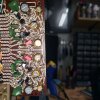 W15-031 Control Amp.jpg144.5 KB · Views: 9
 -
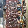 W15-031 Control Amp Foil.jpg166.2 KB · Views: 9
 -
 W15-010 Foil.jpg155.6 KB · Views: 9
 -
 W15-010 Filter Unit.jpg67.3 KB · Views: 8
 -
 Q602 Right Channel.jpg138.5 KB · Views: 7
 -
 Q603 Right Channel.jpg139.8 KB · Views: 7
Last edited:
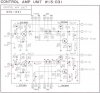

 I even remember reading markthefixer warning about that!!
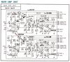
 Today I'm going to go over the power amp board and make sure each cap and transistor is in correctly, and also test everything as zeb recommended, which should be fun since for Christmas my wife bought me a peak transistor tester
  .
.
 Inspected every cap and transistor that I replaced on the main amp board and found C802 was in backwards!


