• The move to the new server is done. There are some software and database maintenance updates in process. This has us passing the hat around to help out. We appreciate any donations. Seriously, even a dollar helps. The payment page may be found here - https://www.audiokarma.org/support.html

SX-1010 Tracking Hiss - Always Present - Especially When Treble Increased

I replaced the 1312's for 1845fta, still the same. Faceplate and hood are off, bottom plate on. It's 3.20am here, time for bed, thank you all for the help, much appreciated!

Ok, this was serious enough for me to start checking.

Control Amp Assembly (AWG-027-0)
AWG-027-0: C1: .33uF 25v: CSSA: 667-ECQ-V1H334JL .33uF 50v
AWG-027-0: C2: .33uF 25v: CSSA: 667-ECQ-V1H334JL .33uF 50v
C1 and C2 are questionable substitutions - I KNOW as a rock solid foundation, the Nichocon UKL caps ARE LOW NOISE. I haven't PROVED that for myself with Panasonic ECQ metallized film caps.

Checking the rest of the substitutions, the rest are OK. CSSA, CEANL are both replaced completely with Nichicon UKL low leakage / noise capacitors.


ECQ's are metallized film and assumed to be low leakage. This part number was listed by Mouser as obsolete and the data sheet does not list the leakage.
it says:
C<=0.33uf : IR>= 3000 megohms
C>0.33uF IR>=1000 megohms.
(me: ) delta V across the caps divided by 1000 megohms for uA leakage.

here's a UKL part number: 647-UKL2AR33KDD 0.33uf 100v 85c
listed as leakage of 0.002 CV or 0.2uA, whichever is greater.

Checking the rest of the substitutions, the rest are OK. CSSA, CEANL are both replaced completely with Nichicon UKL low leakage / noise capacitors.

Frankly, I would try UKL's in those 2 positions and see what my ears tell me.
I DO have a SX-1010 waiting on the shelf, waiting for preamp work (psu and power amp done long ago)
 
Hi Mark, thank you for weighing in. C1 and C2 were replaced with ukl nichicons from what I can tell. Please see picture. Took this before pulling those 6 transistors last night.


DSC_0208.JPG
 
Do i need to just write this off, tone control section is good per the required BOM from what i can tell. Is the noise floor on the SX1010 just like this? From 5 feet away i can hear the hiss, but when the music plays, unless it is a very quiet passage i cant hear it. I do not want to be wasting anybody's time here, or send both myself and you folks on a wild goose chase. Should i just get over it?
 
Last edited:
I wouldn’t write it off if you’re unhappy with the noise. I don’t know what equipment you’re used to using, but I’ve gone through several 1010’s and I’ve not ever felt they have a terribly high noise floor (as you seem to be experiencing). I think it’s worth chasing a bit more, since clearly your ears don’t like it!
 
Ok just checked With jumpers removed very quiet, have to put ear right up to speaker to hear the hiss.
I assume that this removes tge power supply and power amps from the equation?
 
Yes.
It’s going to be tough to sort this out. If it can be.
Both channels.
We’d have to start swapping components with substitutes.
 
OK pretty dumb question, what would happen if the transistors were Changed to slightly lower gain versions? Or is that just stupid talk?
 
If I were investigating, the first thing I now would do is to connect pin 4 to 5 (leave 8 to 9 initially open for a comparison) to quash all extraneous input and look for internally generated noise.

I would (for now) ignore q5, q6, q7 and q8.

It is not normal hiss either, like just the noise floor of the receiver i have had a few receivers now and they have all been dead quiet.

These other receivers? Any of them 1010's?


I have a wild idea: use another unit's phono input as a capacitively coupled (0.1uf FILM) probe,
and start with the isolated internal power busses on the board. (+13v left, +13v right,-13v left, -13v right)

If they are equally quiet, OK - if NOT - go straight to the + / - 56v regulators and check them.
There WILL be SOME noise to be found on them,
but if there is a fault then one (of the SIX: +13v left, +13v right,-13v left, -13v right, +56v, -56v)
will be appreciably worse than the other because they are INDEPENDENT.
 
Copy!
I think I'll try that on this one I have. Although the PS is Ricks design. The whole receiver sounds fantastic and the hiss is nonexistent.
 
No other 1010 receivers, only had sx450, SX550 and a sx750. The only receiver i have now is the Pioneer, others are integrated Onkyo's.

I am sorry but i do not understand how i make up the probe you are talking about. I am fast approaching my technical and electrical limitations here folks.

What board are you talking about connecting pins 4 and 5 together? Power supply board?
 
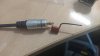
The probe is made with an axial .1uf 400v film cap and a RCA double ended cable. Wrap the lead on one end of the cap around the center probe of the RCA Jack (on the cable) and solder it. Plug the RCA into the right or left channel on an integrated or receiver and turn down the volume. Turn on the unit and with the free end of the cap as the probe (insulate all but the tip to keep "AW ****'s " to a minimum) touching the affected component or circuit, advance the volume until you can hear noise. Now you should be able to listen all over that circuit. Keep the probe handy for other work.
 
Thanks Larry, very much appreciated. Does it have to be 0.1uf and 400v?
Also does it gotta be connected to the Phono input of other amp or will any input do?
 
Last edited:
100 volt will work. The voltage rating has to be over the circuit voltage your probing.
.22-.47uf(?) should be okay. Try it.
 
I'll have a look and see what I have, otherwise I need to order a whole bunch of stuff in order to meet the free delivery requirements.

As one to just throw out there, @zubulon1 what do you think if I went and bought the custom power supply board that one of ak members sells?

I will make the probe though, sounds like I can manage that.
 
Last edited:
The PS is a good deal all a round.
I'll build you one and send it. It wouldn't be much to ship, $25US or so.
 
What board are you talking about connecting pins 4 and 5 together? Power supply board?

Control Amp Assembly (AWG-027-0), pin 5 is the signal reference ground, pin 4 is the signal input.
The grounding means that the only thing coming out of that channel will be internally generated hiss.

The other channel is pin 9 input and pin 8 signal reference ground.

I guess I'll have to make up a list of probe points.
 
Thank you everyone for your patience and help. I hope I am not frustrating you all.
I have made up the probe using a 0.22uf 250v film cap. See attached picture to confirm I have made the probe correctly
15656058688598606823847838500578.jpg
 
Last edited:
Back
Top Bottom