
• The move to the new server is done. There are some software and database maintenance updates in process. This has us passing the hat around to help out. We appreciate any donations. Seriously, even a dollar helps. The payment page may be found here - https://www.audiokarma.org/support.html

SX 1050 Help

jFF_Bulbo

Active Member
Hello AKer´s.

I recently start the SX1050 restoration.
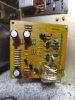
Unit was DOA, and it had several problems.. i show some of them :
QIsx496.jpg

e2KGAuR.jpg

AWR-104 power supply was broken, i fixed it with epoxy, patience and soldering wires point to point on the back of the PCB.
on AWM-090 protecion some resistors was blown.
In the power amp -i guess- the right bias trimpot failed and ruined many other pieces: emiter resistors, output transistors... a lot of pieces ( I HAVE NO PICS OF THIS...). Also here a stavistor had a leg broken, (right channel) i repaired it an protected w/epoxy.

All the described problems has been fixed, i recapped the unit, also many transitsors are new in both power supplies and power amp. 200+ new pieces are installed, main caps and relays are pending to install.

lk3Vzwn.jpg


well. after all this work a have some problems.

1.- dc offset on right channel can´t be adjusted, it is alway about 60mv (power amp working, tested)
2.- bias ok on right channel, on the left it reaches 42V and can´t be adjusted to 50 mV.
3.- protection relay engages too fast, about 1-2-sec... soft stat relay engages inmediately.
3.- preamp is dead, no sound of any source, just a few pops and nothing more. about this, on AWR 103, i have +18v on pin 15 (should be +30v) and -30v on pin 9 (wich is ok....) so i think the is not enought voltage to make the preamp works.
4.- on AWR 103 i have +12v on pin 13-14, shold be 25v....
5.- power amp is a quit hot after 5 minutes runnig the unit.

thank you!!!!!
 

Attachments

  • e2KGAuR.jpg
    e2KGAuR.jpg
    91.5 KB · Views: 18
Register to hide this ad
First off if the bias is getting to 42volts on the left channel do not run the unit anymore if you haven't already you will blow all the work you have done, first thing to do disconnect all wires from the power supply other than the input voltages, and make sure you have the correct voltage on every pin feeding out to other boards. My guess is your missing a few voltages.
 
Unplug the output transistor connectors from the power amp boards, and get all the power supply voltages (AWR-103) working correctly before you try any other troubleshooting.

FWIW, some of the supplies depend on their load being attached for them to be the correct voltage.
 
protection board has a 33v zener (D5) that through R25 regulates the protect power.

when time is too fast, usually that zener is not regulating 33 volts and protect power is far closer to 60 volts,

another vote for getting the power supplies correct first.

luckily for you the three major power supply sections are independent.

first get the pin 16 +60v working, the pin 15 +30v is dependent upon the +60, and will be half of pin 16 voltage
pin 13 +25v will be 5v less than pin 15

next get the pin 8 -60v working, again pin 9 -30v is dependent upon the -60, and will be half of pin 8 voltage
pin 10 & pin 11 are dependent upon loading
pin 7 is the controlling zener voltage

pin 5 +13v is it's own regulator, and a precise ratio is fed to q12,q13 to
make the 5.4v - so until the +13 is right - don't sweat the +5.4v
 
First off if the bias is getting to 42volts on the left channel do not run the unit anymore if you haven't already you will blow all the work you have done, first thing to do disconnect all wires from the power supply other than the input voltages, and make sure you have the correct voltage on every pin feeding out to other boards. My guess is your missing a few voltages.
hello,. thank you!! bias is 42mV ... typo error..... at this day i,ve changed 6 small transistors (2sa750 subs with ksa992) on power amp......
 
Unplug the output transistor connectors from the power amp boards, and get all the power supply voltages (AWR-103) working correctly before you try any other troubleshooting.

FWIW, some of the supplies depend on their load being attached for them to be the correct voltage.
hello
thank you. today i did just like you recommend. Power transistors removed.... the failure continues. I checked AWR-103 again and it has -30v ok on pin 9, but pin 15 wich should have +30 only has +17.25V......
After that, i measured pin 1 on awr-103... it shold be +24v, but only 17v obtained.
this 24v comes from AWR-104 (which was totally broken........) pin 8. To my sadness, the low voltage is here. anly 17v.....
 
placa de protección tiene un zener de 33v (D5) que a través de R25 regula la potencia de protección.

cuando el tiempo es demasiado rápido, generalmente ese zener no está regulando 33 voltios y la energía de protección está mucho más cerca de 60 voltios,

otro voto para obtener las fuentes de alimentación correctas primero.

por suerte para usted, las tres secciones principales de la fuente de alimentación son independientes.

primero haga funcionar el pin 16 +60v, el pin 15 +30v depende del +60, y será la mitad del voltaje del pin 16
el pin 13 +25v será 5v menos que el pin 15

a continuación, haga funcionar el pin 8 -60v, nuevamente el pin 9 -30v depende del -60, y será la mitad del voltaje del pin 8
pin 10 y pin 11 dependen de la carga
pin 7 es el control de voltaje zener

pin 5 +13v es su propio regulador, y se alimenta una relación precisa a q12,q13 a
haz el 5.4v - así que hasta que el +13 sea correcto - no te preocupes por el +5.4v
Hello and thank you for such a great explanation!
On AWR-103, 2sc869 sub with ksc1845. it works a few better on voltages... but not enough
+60v pin 16 ..... ok
+30v FAIL..... anly 17v
-60v pin 8 .....ok
-30v pin 9 .... ok
+24v pin 1 FAIL. only 17v
 
hello.
After a while with this project paused, i recently are ready to continue working on it.
A few days ago a new AWR-104 (power supply) arrived and now installed. The previous one works well, but on eBay i found a nice piece and the seller send this already recapped!!

well. in a deep search for the reason i have only +20v in AWR-103 pin 15 instead the 30v. i found this:
WR6khi7.jpg


you can see the "+" sign in the pcb where is the cap´s negative.

I hope this solve the voltage problem.
will report this on the next few days.

regards
 
I don't always trust the pcb markings, but in this case, the schematic shows it being correct and that the cap is in backwards. Good eyes!
 
Hello all.
A little question.
In a 1050 working well.....
Do i have to hear both relays clicking when power on?
Soft Star relay no click....
Speakers protección relay ... Click.
Unit conected to DBT. sound comes out from headphones Jack.

Or the soft Star relay must work like that, no clicking????
Regards.
 
need to listen carefully for soft start click.

NO soft start click is a bad thing, the 3.3 ohm 20w resistor will STAY in circuit, strangling the receiver and overheating badly
eventually it will get hot enough to pop the micro temp THERMAL fuse, shutting down the unit completely.

A microtemp is a PITA to find (buy) and even worse to solder it into place - the heat of soldering will pop it
so the leads have to be carefully heat sunk - and that makes it almost impossible to solder in with a low wattage iron.
BTDT

it's a whole lot easier to NOT pop it in the first place.
 
Last edited:
Put your finger on the soft start relay and power the receiver on. You should feel the relay click.
 
Back
Top Bottom