• The move to the new server is done. There are some software and database maintenance updates in process. This has us passing the hat around to help out. We appreciate any donations. Seriously, even a dollar helps. The payment page may be found here - https://www.audiokarma.org/support.html

SX-1250 AWH-048 won't pass dim bulb.

drmazzei

Member
I am testing a Pioneer sx-1250 and everything passes dim bulb except for the left channel. I am using a new 106 board purchased from Delta9Electronics. Rick has been very helpful and patient with me as I tested this board after installing the components. When I switch 048 boards, the "good" right board doesn't pass dim bulb when installed on the left side. Also, when I move the other 048 board to the right side, it passes dim bulb. I have tested continuity on the wires that hold the power transistors and verified that the 21193 and 21194 transistors are installed correctly and pass muster with my Atlas tester. I'm not sure what I should do next to track down this short.
 
Register to hide this ad
I've never been inside a SX-1250 but it sounds like the 048 boards are both fine and there must be something wrong with either the wiring to the PCBs or the signal to the left PCB must be jacked up.
 
If you removed the heatsink it's easy to pinch the unregulated wires between the sink and chassis.
The big bulk filters could be installed backwards.
Double check the outputs PNP/NPN to the correct upper Molex connections. The NPN's should be the violet ,brown, orange wires and the PNP's, the red, white and blue.
Double check for proper output socket alignment to the heatsink. If cocked the transistor will short to the sink. Use your meter in ohms and go between the output case and chassis. With the Molex unplugged all four should read open.
 
Thanks for all your help and input.
1. Checked all the wires one at a time with dim bulb power up and all passed,
2. I am assuming that the Ohm test with the DMM is chassis ground and the case of each to-3 transistor (with all molex connectors unplugged), in which case all read OL.
3. The bulk filters are the giant 22k uf filter caps or particular caps on the 048 board?
4.The PNP and NPN outputs are matched to correct color molex connectors.
5. Could a jacked up signal to the left PCB emanate from failing transistors on the equalizer board?
 
Recap ?:
Both amp boards work when connected to the right heatsink and outputs.
The left heaksink assembly with the outputs causes the dim bulb to go bright no matter which amp board is installed.
So:
The right amp works with either amp board?
The left side amp outputs and heatsink, when connected cause a bright bulb when powered up?

My list of checks in post 4 is all the things that could go wrong with the output assembly. Pinched unregulated wires, backwards filters and outputs would cause an instant bright bulb when powered up. If the bulb stays dim without the amp connected the chassis is considered good.

You could install one of the amp boards but only plug one Molex output plug (Top plugs, pins 8-12 and 15-18) in one at a time, hopefully narrowing down, at least what output pair on the sink is causing the bright lamp?
 
Only when Molex plugs that connect to pins 15-18 and pins 9-12 installed at same time does the the dim bulb stay bright. When 9-12 or 15-18 are installed separately unit passes dim bulb. The previously new installed giant filter caps all seem to be in the correct orientation.

Yes, both 048 boards work only on the right side and not on the left.
 

Attachments

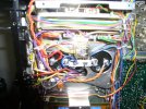
  • SX-1250 L ch new filter caps bottom.JPG
    SX-1250 L ch new filter caps bottom.JPG
    151.6 KB · Views: 13
  • SX-1250 R ch new filter caps bottom.JPG
    SX-1250 R ch new filter caps bottom.JPG
    145.5 KB · Views: 13
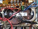
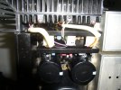
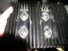
Images of the right amp and heatsink from the top and one from the side including the outputs with the grill covers off.
id like to see the outputs numbers.
 
P1010394.JPGP1010394.JPGP1010396.JPG

After rechecking how all things were installed, I A/Bd right amp and left amp wires and looked at restoration photos on various AK threads. I figured out that the two Molex plugs 9-12 and 15-18 weren't connected correctly because the MJ21193s and 21194s were switched. Upon fixing this issue, the unit passes dim bulb. However, now when biasing the amps, I cannot get 100mv on either channel (Rt is 25mv and Lt is zero), The 0v to the speaker outputs is ok.
 
With the MJ's as outputs you can't reach 100mv's. This is normal when using the MJ's. We normally set the bias to 65mV's with the On-Semi's.
The better MJ choice is the MJ21195-96's for the 1250's You might consider replacing them. The spec's are virtually the same but they do make a difference in performance.
 
I changed the outputs to MJ2195 and MJ21196. I am still getting 0mv for bias and the new 500 Ohm VR2 pot will not adjust the value at all.

Previous changes:

C11 to film WIMA 0.22uf @ 63v.
C2 C5, C15, and C16 electrolytics.
Q1, Q2 to Hfr exact matched ksa992s.
Q11 was changed to ksc1845FTA.
Q3-Q6 tested good and weren't changed (ksa 1381 unobtainium)
Diodes D5,D8,D9 were changed to 1N41418.
Diodes D3, D4, D6, D7, D10, D11 are now 1N4004.
 

Attachments

  • P1010400.JPG
    P1010400.JPG
    126.6 KB · Views: 10
  • P1010401.JPG
    P1010401.JPG
    163.2 KB · Views: 8
  • P1010403.JPG
    P1010403.JPG
    121.5 KB · Views: 10
  • P1010404.JPG
    P1010404.JPG
    135.6 KB · Views: 11
The bias uses the +-65 regulated from the stabilizer.
Do you have voltage at pins 2 and 3 of the 048 boards?
 
Measured @ AWR-106-B0: +65.0, -65.7.

#2 #3
048 Rt -65.9 63.7
048 Lt -65.5 64.0

AWR-106-B0: Q5 B=-65.9, Q5 E=-65.3, Q7 B=-66.5.

Only upgrade on Right 048 board are caps C2, C5, C15, C16, and C11 (everything else original).
 
If you had outputs incorrect, you could have damaged your pre-drivers Q7/8 or drivers Q9/10. That would keep the amp from being able to set bias.
 
If you had outputs incorrect, you could have damaged your pre-drivers Q7/8 or drivers Q9/10. That would keep the amp from being able to set bias.
Not likely.
More likely, you’re not set up correctly with either the meter or on the correct test pins.
Please verify your 048 pin voltages. You posted both negative.
 
Ok, back again. Voltaqes left AWH-048 board. #2 is 65.4 vdc and #3 is 64.8 vdc. Note that i was able to bias right amp board to proper setting.
 
Left board:
Is pin #2 negative?
Did you have shorted outputs before you started?
 
You may have a poor solder joint somewhere- start at the test pins amd go through each one all the way to STV on top side. Reflow those, and the budges that run under the board heatsink too. I would suspect VR2 but you said you replaced that and they don't usually stay 0 if failed, they rise steadily on these units. I'm still thinking its a bias transistor- keep in mind that sometimes you can test it and it seems fine, but once they are energized they act up.
 
Back
Top Bottom