

You are using an out of date browser. It may not display this or other websites correctly.
You should upgrade or use an alternative browser.
You should upgrade or use an alternative browser.
SX-1250 - Distortion at low volume
- Thread starter ekooch
- Start date

You could arrange another signal source, with a controllable level (another receiver?) and feed it into the power amp in connections to see if the muddiness is a property of the power amps.
You could also take the pre-out of the unit and run it into another amplifier to see if it is sending a clean signal to the amplifier.
We can also check the other, lower power supply voltages that run other circuits, not the power amps.
You could also take the pre-out of the unit and run it into another amplifier to see if it is sending a clean signal to the amplifier.
We can also check the other, lower power supply voltages that run other circuits, not the power amps.
It's an amp problem. I just tried connecting the preamp outputs to a Cambridge Soundworks powered sub/sat system and there was no distortion. I previously connected a KLH Model Eighteen preamp/tuner to the amp section of the 1250 and heard distortion.
To go off topic for a second, the CSW system sounded pretty good connected to the 1250 preamp. I had been using the KLH Eighteen and the CSW system in the bedroom - sort of a Henry Kloss old/new combo....
To go off topic for a second, the CSW system sounded pretty good connected to the 1250 preamp. I had been using the KLH Eighteen and the CSW system in the bedroom - sort of a Henry Kloss old/new combo....
Well, it IS a strong step forward when you KNOW the problem is limited to the power amp stages.
As for the amps, we know they only share the two regulated supply voltages, and because the output power for both channels is also isolated, that's all they share, while the symptoms are on BOTH channels.
I hate to say it, but my first suspicion falls upon the actual output transistors. I won't carp about wishing I had better instruments. These should probably be the last big ticket items at about 4 (replace the mica insulators at $0.16 ea x 8) bucks apiece running about 33 bucks before shipping. The driver transistors should go for less than a buck apiece, trimpots (if needed) 1 to 3 bucks each, caps at 25 to 50 cents each and the small signal transistors under a quarter each.
Here's a post I did on sx-1250 amp replacement transistors a short time ago
here's the insulators and thermal grease:
ten: 534-4662 to-3 mica insulators $0.16 each (two spares)
six: 534-4672 to-220 mica insulators $0.12 each
one: 532-249 1 oz thermal compound $4.71
I don't yet know which * letter designation and thus the parts number for the four identical trimpots at 470 ohms, for both bias and offset adjust. Since you are going in there anyway.
as for the capacitors:
four 470uF/80v 647-UPW2A471MHD @ 1.92 ea nichicon pw
two 10/16 647-UVZ1V100MDD @ $0.06 ea nichicon vz
two 220/16 647-UVZ1E221MPH @ $0.35 ea nichicon vz
at this point, there's not much left original....
I don't think we should worry about the diodes....
This is just so you can plan ahead.
There would be a few more parts for beefing up/renewing the protection circuits...
so it's not quite ready to order out yet...
As for the amps, we know they only share the two regulated supply voltages, and because the output power for both channels is also isolated, that's all they share, while the symptoms are on BOTH channels.
I hate to say it, but my first suspicion falls upon the actual output transistors. I won't carp about wishing I had better instruments. These should probably be the last big ticket items at about 4 (replace the mica insulators at $0.16 ea x 8) bucks apiece running about 33 bucks before shipping. The driver transistors should go for less than a buck apiece, trimpots (if needed) 1 to 3 bucks each, caps at 25 to 50 cents each and the small signal transistors under a quarter each.
Here's a post I did on sx-1250 amp replacement transistors a short time ago
Mouser parts numbers, a mix of Fairchild (512-) and ON-Semi (863-)
differential inputs, better off if the hfe is matched
2sa750 to-92 ecb 50v .05a .25w 100mhz hfe:450
512-KSA992FBU (ln)to-92 ecb 120v .05a .5w 100mhz 150-800hfe $0.05 ea
bias / vas
2sa858/2sc1439 to-92 ecb 150v 0.5a .5w 100mhz hfe:150 better off if the hfe is matched here too on the 858 / 2310s
512-KSA910YBU to-92 ecb 150v .05a .8w 100mhz 40-240hfe $0.12 ea
512-KSC2310YBU to-92 ecb 150v .05a .8w 100mhz 40-240hfe $0.11 ea
pre-driver
2sa899/2sc1904 to-126 ecb 150v .05a 1w 100mhz hfe:150
512-KSA1142YSTU to-126 ecb 180v .1a 1.2/8w 200mhz 100-320hfe $0.28 ea
512-KSC2682YSTU to-126 ecb 180v .1a 1.2/8w 200mhz 100-320hfe $0.31 ea
drivers
2sb630/2sd610 to-220 bce 200v 2a 25w 4mhz hfe:80
512-KSA940TU_Q pnp to-220 bce 150v 1.5a 25w 4mhz 40-140hfe $0.54
512-KSC2073TU npn to-220 bce 150v 1.5a 25w 4mhz 40-140hfe $0.54
power outputs
2sb600/2sd555 to-3 200v 10a 200w 14mhz hfe:70
863-MJ21194G to-3 NPN 250v 16A 250W 4mhz 8-75hfe $4.10
863-MJ21193G to-3 PNP 250v 16A 250W 4mhz 8-75hfe $4.10
here's the insulators and thermal grease:
ten: 534-4662 to-3 mica insulators $0.16 each (two spares)
six: 534-4672 to-220 mica insulators $0.12 each
one: 532-249 1 oz thermal compound $4.71
Bourns 3386* for single turn trimmers at about $ 1.15 ea
Bourns 3296* for 25 turn trimmers at about $ 2.37 ea
Bourns 3266* for 12 turn trimmers at about $ 2.92 ea
The * substitutes a letter designation for the lead pattern and which way the adjustment faces when installed.
available at mouser.com and digikey.com and lots others.
I don't yet know which * letter designation and thus the parts number for the four identical trimpots at 470 ohms, for both bias and offset adjust. Since you are going in there anyway.
as for the capacitors:
four 470uF/80v 647-UPW2A471MHD @ 1.92 ea nichicon pw
two 10/16 647-UVZ1V100MDD @ $0.06 ea nichicon vz
two 220/16 647-UVZ1E221MPH @ $0.35 ea nichicon vz
at this point, there's not much left original....
I don't think we should worry about the diodes....
This is just so you can plan ahead.
There would be a few more parts for beefing up/renewing the protection circuits...
so it's not quite ready to order out yet...

Arkay
Lunatic Member
At some point, I need to completely re-furbish an SX-1250, too. It works, but that isn't the same as working "as well as when new". Reading this thread (and especially the previous post!) reminds me of why I have been putting it off. Wish shipping around the planet to EW wasn't so expensive and fraught with risks. Have to wait until I'm really in the mood for a major project. Sigh...
The capacitors, resistor and thermal fuse have all arrived. I can probably start later this week on these but I haven't ordered anything else yet. The bias pots are still at their limit of adjustment. Should I back them off before I install any new parts to avoid further problems?
The capacitors, resistor and thermal fuse have all arrived. I can probably start later this week on these but I haven't ordered anything else yet. The bias pots are still at their limit of adjustment. Should I back them off before I install any new parts to avoid further problems?
If the heatsinks aren't getting hot, I would leave it alone...
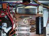
The new capacitors are installed. I was going to do the resistor/thermal fuse change but I'm not sure what to do about the fuse next to it wrapped in duct tape. This fuse is not present on pictures of other 1250's - it was probably part of the 'workaround' someone did at one time.
Attachments

jeffn
Mid-Fi Crisis
The new capacitors are installed. I was going to do the resistor/thermal fuse change but I'm not sure what to do about the fuse next to it wrapped in duct tape. This fuse is not present on pictures of other 1250's - it was probably part of the 'workaround' someone did at one time.
I'd guess the fuse is blown and only there to hold the duct tape in position. The foil on the tape is being used as a fuse (looks like its started to fry as well, since it's probably too much of a resistor). Get rid of the tape and install a good fuse.
I haven't read all the other posts so forgive me if this has already been said.

That goofy fuse is installed where the thermal fuse is supposed to be. Install the new power resistor, and then install the thermal fuse, tying it physically to the power resistor so if the resistor gets hot (which is never supposed to happen in normal operation) the fuse opens and the unit shuts down.I was going to do the resistor/thermal fuse change but I'm not sure what to do about the fuse next to it wrapped in duct tape.
The new capacitors are installed. I was going to do the resistor/thermal fuse change but I'm not sure what to do about the fuse next to it wrapped in duct tape. This fuse is not present on pictures of other 1250's - it was probably part of the 'workaround' someone did at one time.
That duct tape was probably to shield the fuse from the heat of the resistor, which SHOULD NOT be happening....
The resistor had the thermal fuse mounted inside or tied to it originally (IIRC) and this assembly should ONLY run for a few seconds at powerup, and it whould never generate this much heat over only those few seconds.
It is ESSENTIAL to physically verify that the soft start relay IS operating mechanically, then also to verify it electrically. While the resistor is OUT, and the unit is UNPLUGGED, close the relay manually and measure the contact resistance which is available across pins 1 and 2 now that the resistor isn't shunting them.
MY bet is that the contacts are burned up, OR the relay ISN'T operating, leaving that resistor ALWAYS in circuit, burning things up.
Also check R9, the 2.2k resistor, 2 watt resistor. It's near pin 13 on the other side of the board from the resistor and fuse combination.
The relay is working mechanically but I'm not sure my readings make any sense. I had the red connected to pin 2 and the black to pin 1. The meter was set to 200 ohms. The reading fluctuated when I first closed the relay - it was positive sometimes and negative other times but it always went to 0 within a second. For R9, I had the meter set to 2k ohms and it read 1.99 - 2.01 (fluctuating) and it didn't seem to matter if the relay was open or closed. Thanks again for the help.
Update: I installed the resistor and thermal fuse. I tried not to apply too much heat to the board but I must have messed up because the 1250 will not power up - no lights, no clicks, nothing. Is the thermal fuse directional? Or, is it possible that the soldering process burnt the fuse? I hope I didn't cause any major damage.
Update: I installed the resistor and thermal fuse. I tried not to apply too much heat to the board but I must have messed up because the 1250 will not power up - no lights, no clicks, nothing. Is the thermal fuse directional? Or, is it possible that the soldering process burnt the fuse? I hope I didn't cause any major damage.
Last edited:
To protect a thermally sensitive component when soldering, something metal (pliers, hemostats etc) is clamped on the wire between the solder joint and the component.
Take ohmmeter readings of the fuse, it should be close to zero ohms. Sounds like it was popped on installation.
Take ohmmeter readings of the fuse, it should be close to zero ohms. Sounds like it was popped on installation.
That was it - too much heat got through during soldering. I used a clamp-on heat sink on the new fuse and it's fine. I guess I can get back to the list of components to order from Mouser...and some more studying of the service manual. I won't submit the order yet in case there's more to add to it.
That was it - too much heat got through during soldering. I used a clamp-on heat sink on the new fuse and it's fine. I guess I can get back to the list of components to order from Mouser...and some more studying of the service manual. I won't submit the order yet in case there's more to add to it.
The overriding concern at this point is that the new parts you put in don't heat up and burn out again because they are continuously in circuit, instead of only being used for a few seconds to control the tremendous inrush of current to charge the capacitors when it is first turned on....
If they get HOT (check with the power plug OUT :yes
 , then we probably will have to replace the relay, since you indicated that it appears to be mechanically actuating.
I powered it up and left it on for about 40 minutes. I checked the resistor and it was still at room temperature. I wish I had the whole history on this unit so we'd know why the original resistor was burnt and what else was done when they replaced the thermal fuse with the glass fuse.
Ok, this is a sx-1250, it's original complaint was low level distortion. The main capacitors looked like they had leaked, and had suspect measurements so they were replaced. Were all four capacitors done? If so a repeat of the mesaurements (dc and ac voltages across all four sets of screw terminals) will give us a valuable baseline.
We veered off track a bit correcting a problem with the soft start resistor and thermal fuse, which now appear to be operating correctly.
So we're back onto the distortion problem, which we narrowed down to the power amps. The bias current for the amplifiers was low and could NOT be brought up to specs.
Due to shipping cost considerations for shipping the entire unit we are leaning towards shotgunning the amps, starting with the output transistors and working back. Since the outputs represent the major costs of the replacement transistors, and the rest of the transistors cost significantly less than the postage to ship them, we were going to get a complete set of outputs and all other amplifier transistors...
We were also going to get replacements for the few capacitors used, as well as replacing the trimpots with new and possibly multi-turn units.
We may have a few issues to resolve in the choice of the trimpots as to the number of turns and what direction the adjust points in (for access).
Plus I am going to look at the diodes, at $0.10 each, what the heck..
1s1886 = 1amp 200v . uf4004 = 400v 1 a fast recovery
so we'll rehash the parts here, possibly yet today, coming up with the list including quantities... (ok?)