• The move to the new server is done. There are some software and database maintenance updates in process. This has us passing the hat around to help out. We appreciate any donations. Seriously, even a dollar helps. The payment page may be found here - https://www.audiokarma.org/support.html

SX-1250 question

ocdecio

The proof of the restoring is in the listening.
Subscriber
This is the first Pioneer I put my hands on, for a friend (I am a Marantz guy through and through). This receiver is really well built I mus say and it doesn't seem all that hard to work on except of course for its sheer monstrous size.

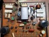
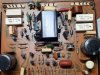
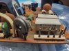
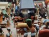
Anyway, I tried checking bias with a DBT and right channel although unstable gave some voltage, and left nothing. I pull the cards out and this is what I found.

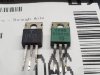
Can anyone help me understand what may be going on here? It see,s to me these klugde resistors are not original on left channel nor are these two TO220 transistors. However the set of resistors on the left side seem original, but I see two in the right board and four in the left so this is a real head scratcher. Also the bias trimpot looks out of place.

I appreciate any information from someone that worked on these.
20220721_135702.jpg 20220721_135820.jpg 20220721_135826.jpg
 
Register to hide this ad
Have you downloaded the service manual? It is absolutely essential.

Those are 220 ohm resistors, paralleling two of them would give 110 ohms at double the wattage. Somebody didn't have 100 ohm 1 watt resistors....

The to-220 transistors are stuffed into two pre-driver locations, the originals were TO-126 cased transistors, as you can see from the other boards.
Again, somebody didn't have the proper parts, and had no patience to wait.

All in all the replacement of that trimpot suggests there is problems in the thermal bias diode circuit. WHEN that circuit fails (broken wire, bad spot on trimpot etc..) both halves of the push pull driver turn on HARD, with lots of smoke and even wire damage.

With dead outputs, you should check ALL the 0.5ohm 5 watt resistors (big white rectangular things) because they will prevent a repair from working.

Now, about this "broken wire"
there is a component connected to this board (top, center of edge) that mounts on the heat sink. The thermal diode, it reduces the drive to the output transistors when they are hot.
The wires on this thermal diode are brittle, and break off flush on the component.
NOT good,, boom, zappp, smoke and flames....
never bend the thermal diode wires closer than 1/2" from the case.

From the carnage, I expect that was the original problem. A bad spot on the trimpot, causing an open-circuit condition.
Ate the 100 ohm 1 watt resistors, ate the paralleled 220 ohm resistors...
 
Last edited:
It sounds like after you take @markthefixer (guy is a wizard) advice, a complete rebuild of the stabilizer board may be in order. There maybe many damaged components. I would pull the driver boards and just rebuild the stabilizer to see if you can get reasonable operation before testing the full receiver.
 
Thank you so much, @markthefixer ! I am glad I asked and I appreciate the detailed answer. I will look for broken connections to what I belive is the triple diode (Marantz uses them extensively). Lots of the transistors seem to sub to ones used in Marantz as well so I may have them in stock. I'll see about getting new Bournes trimpots too.

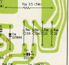
On the "good" board, R35 and R34 are missing. They seem to be important?

upload_2022-7-21_16-9-38.png


I actually got both the physical, original users and service manual and I am reading through them and AK before I go any further.

Later I may need to ask about the other channel that has wild oscillations in the bias circuit even though the board looks original (it goes up to 2V or so - all under a 150W dbt lamp).
 
Last edited:
It sounds like after you take @markthefixer (guy is a wizard) advice, a complete rebuild of the stabilizer board may be in order. There maybe many damaged components. I would pull the driver boards and just rebuild the stabilizer to see if you can get reasonable operation before testing the full receiver.
Thank you for the advice. I measured almost --65 and +65 V at the stabilizer board (under 150W dbt lamp) so I hope that board is not damaged, but yes it will get a full restoration.
 
Thank you for the advice. I measured almost --65 and +65 V at the stabilizer board (under 150W dbt lamp) so I hope that board is not damaged, but yes it will get a full restoration.

So the stabilizer is giving you +-65v even with the burnt parts?
 
The burn parts are in the left power amplifier AWH-048A board. The stabilizer only has some caps with shrunk sleeves.

Oh, my bad - I looked quickly at the pics and assumed we were talking stabilizer. Should have looked closer. But the stabilizer should probably be rebuilt. Mine went out about a year ago (matter of when not if) and I gave it a complete redo.
 
Oh, my bad - I looked quickly at the pics and assumed we were talking stabilizer. Should have looked closer. But the stabilizer should probably be rebuilt. Mine went out about a year ago (matter of when not if) and I gave it a complete redo.
No worries! Yes, the stabilizer/power supply is a must on any unit, Marantz are no different in that regard.
 
Yes, the missing resistors are important.
The 22 ohm resistors sum the emitter voltages of the output transistors, for two things:
1. pins 7 & 19 for reading idle current
2. over current protect.... i.e. too much speaker load on that channel.
 
Yes, the missing resistors are important.
The 22 ohm resistors sum the emitter voltages of the output transistors, for two things:
1. pins 7 & 19 for reading idle current
2. over current protect.... i.e. too much speaker load on that channel.
Thank you again! Someone did a number on this receiver apparently. And the wrong subs seem to be obsolete so it must have been a while ago.
 
With dead outputs, you should check ALL the 0.5ohm 5 watt resistors (big white rectangular things) because they will prevent a repair from working.

I assume they can be replaced with 0.47ohm? I don't think the 0.5 are still available.
 
.5 ohm are available. Either find them from Mouser or Digi-Key, or I have them available on eBay. I never change ohm values on emitter resistors--it changes the math on bias.

Ideally every SX-1250 should have the complete stabilizer board, protection board, power supply board (underneath), and both amp boards rebuilt. New electrolytic caps, all transistors (except drivers and outputs unless necessary), all diodes except the obvious STVs, ALL relays, all trimmers. There's so much stuff that gets cooked over the years, it's worth redoing all of this. Make sure you get the soft-start relay along with everything else.
 
.5 ohm are available. Either find them from Mouser or Digi-Key, or I have them available on eBay. I never change ohm values on emitter resistors--it changes the math on bias.

Ideally every SX-1250 should have the complete stabilizer board, protection board, power supply board (underneath), and both amp boards rebuilt. New electrolytic caps, all transistors (except drivers and outputs unless necessary), all diodes except the obvious STVs, ALL relays, all trimmers. There's so much stuff that gets cooked over the years, it's worth redoing all of this. Make sure you get the soft-start relay along with everything else.
Again, glad I asked and thank you. Yes, this will be a full restoration, no stones unturned. This is one reason I asked about the resistor, what it is currently installed on one side (the other side is indeed 0.5ohm)

Now one question I always ask myself - should the unit be first fixed and then restored or would the restoration itself help remove most issues and therefore should come first?

20220722_110744.jpg
 
That's not original. That trimmer doesn't look original either. Same with those carbon comp resistors. Someone really put a LOT of effort into that one, back in the day. Those look like 1970s or 1980s parts to me.
 
That's not original. That trimmer doesn't look original either. Same with those carbon comp resistors. Someone really put a LOT of effort into that one, back in the day. Those look like 1970s or 1980s parts to me.
Indeed! Even the (wrong) predriver subs were totally obsolete parts. One of them is actually an original driver part:

20220722_111509.jpg
 
After replacing the current mirror, diff pair and bias transistors plus some resistors I am now able to fully control bias under a 150W dbt, and DC offset is low (working on the left channel only).

Is it now safe to plug it on the wall and finalize the adjustments? Should I first try to put some signal under the DBT?

My apologies for sounding overly cautious but this is my first Pioneer and a big one at that. Thanks!
 
Caution is commendable. And usually rewarded.

The other, right channel : can you control DC offset and set idle current? if yes, you're ready to ditch the DBT.

if not, you're halfway there.

Trial sets of idle current (one channel at a time!!) under DBT ("tickling the dragon's tail") are important to tease out any faults.
Just remember that on DBT the current must be returned to zero at the end of that channel's test,
if that setting were allowed to receive straight line power, it would be way too high - probably damagingly so.

Also dialing up idle current on the DBT makes DBT glow brighter and as that happens the ac TO the unit is strangled more.
Protects have been known to be triggered with the lower ac voltage.
You can increase the wattage of the DBT, there is no reduction in what the DBT is protecting from.
Another lamp in parallel with the first lamp.
 
Back
Top Bottom