• The move to the new server is done. There are some software and database maintenance updates in process. This has us passing the hat around to help out. We appreciate any donations. Seriously, even a dollar helps. The payment page may be found here - https://www.audiokarma.org/support.html

SX-1280 Power Supply Assembly (AWR-157) Question...

sbparks

Active Member
Hi Folks,

I know this topic has been discussed a bit, but I can't seem to find the specific threads.

I want to rebuild my power supply board for this unit. I see evidence of scorching of the board due to the quite warm (hot) transistor and several of the capacitors have seen better days. I believe everything to be original.

I see the parts lists for this board, so I am all set there. My question is that I've seen where some of these hot transistors get relocated to the main heat sink. Is there a specific part that I can order to accomplish this relocation? I'm asking about the new length of wire I'll need... is there a three wire 'remote location' setup that would allow the leads of the transistor to plug into the new wire harness?

If so, this would be a nice neat assembly. Otherwise, I'll would just need to attach the wires to the legs of the transistors and use some heat shrink to keep everything safe.

I know I would need the thermal paste and insulator as well.

One thing that might help me research better... The hot transistor on that board (for me, it is Q2, 2SB682-D)... That style of transistor - I think you call it 'the package'... What is that style/shape of transistor.

I appreciate any information and suggestions as far as this project. Thanks.

Scott

BTW, my 1280 still sounds great. I just hate to see this power supply looking the way it does.
 
Register to hide this ad
Hi Folks,

I know this topic has been discussed a bit, but I can't seem to find the specific threads.

I want to rebuild my power supply board for this unit. I see evidence of scorching of the board due to the quite warm (hot) transistor and several of the capacitors have seen better days. I believe everything to be original.

I see the parts lists for this board, so I am all set there. My question is that I've seen where some of these hot transistors get relocated to the main heat sink. Is there a specific part that I can order to accomplish this relocation? I'm asking about the new length of wire I'll need... is there a three wire 'remote location' setup that would allow the leads of the transistor to plug into the new wire harness?

If so, this would be a nice neat assembly. Otherwise, I'll would just need to attach the wires to the legs of the transistors and use some heat shrink to keep everything safe.

I know I would need the thermal paste and insulator as well.

One thing that might help me research better... The hot transistor on that board (for me, it is Q2, 2SB682-D)... That style of transistor - I think you call it 'the package'... What is that style/shape of transistor.

I appreciate any information and suggestions as far as this project. Thanks.

Scott

BTW, my 1280 still sounds great. I just hate to see this power supply looking the way it does.
The 2SB682 is a TO-220 package. Pioneer power supplies seem to almost always run HOT. They pushed components to the limit. Some of the parts get hot enough to compromise the solder joints over many years of thermal cycles. It does not help that a lot of them are mounted upside down so the heat goes right into the PC board.
And a lot of them don't have good ventilation either.
 
I would rebuild it to the Pioneer forums specs and call it good.
You can always improve the cooling but in this case its wasted effort.
When all is corrected with new modern transistors and proper bench practices it will run fine for many years.
The furthest I would go, is to install the newer snap in heatsinks which will improve the heat sheading as long as they fit in the space.
 
Hi Folks,

I know this topic has been discussed a bit, but I can't seem to find the specific threads.

I want to rebuild my power supply board for this unit. I see evidence of scorching of the board due to the quite warm (hot) transistor and several of the capacitors have seen better days. I believe everything to be original.

I see the parts lists for this board, so I am all set there. My question is that I've seen where some of these hot transistors get relocated to the main heat sink. Is there a specific part that I can order to accomplish this relocation? I'm asking about the new length of wire I'll need... is there a three wire 'remote location' setup that would allow the leads of the transistor to plug into the new wire harness?

If so, this would be a nice neat assembly. Otherwise, I'll would just need to attach the wires to the legs of the transistors and use some heat shrink to keep everything safe.

I know I would need the thermal paste and insulator as well.

One thing that might help me research better... The hot transistor on that board (for me, it is Q2, 2SB682-D)... That style of transistor - I think you call it 'the package'... What is that style/shape of transistor.

I appreciate any information and suggestions as far as this project. Thanks.

Scott

BTW, my 1280 still sounds great. I just hate to see this power supply looking the way it does.
Buy a new board on eBay from delta9electronics, an AK member. No rebuild will ever completely solve the amount of heat generated.

I've bought many boards from him and they are worth every dollar.
 
I appreciate the replies.

Zebulon1... What are the 'Snap On' heat sinks you refer to? I'll search up on Mouser if I know what to look for. I took note of the HS300-ND Digikey heatsinks for the TO-220 package. They look like an improvement over what is currently being used.

Ivan... I saw those new power supply boards. That does look like a winner with the modern parts. I didn't know he was on eBay. Thanks.
 
Something like Aavid's 566902B could dissipate enough heat, but verify that you have the space.
 
I've decided to rebuild my power supply board with new capacitors and transistors. I used the BOM and ordered the parts for this board.

Yesterday's effort was to remove the board from the unit and then to remove each component from the board. I took my time and (most) everything is off.

The large capacitors were glued in place. I was able to lift them with no damage to the board. I see plenty of posts about cleaning these circuit boards, but nothing that indicates if there's a safe way to remove this glue residue. Is there a solvent I can use that will aide in this process?

Surprisingly, most of the glue is actually malleable. If it were brittle, I think I could push it off the board using a blunt edge.

Thanks for any suggestions!
 
I've decided to rebuild my power supply board with new capacitors and transistors. I used the BOM and ordered the parts for this board.

Yesterday's effort was to remove the board from the unit and then to remove each component from the board. I took my time and (most) everything is off.

The large capacitors were glued in place. I was able to lift them with no damage to the board. I see plenty of posts about cleaning these circuit boards, but nothing that indicates if there's a safe way to remove this glue residue. Is there a solvent I can use that will aide in this process?

Surprisingly, most of the glue is actually malleable. If it were brittle, I think I could push it off the board using a blunt edge.

Thanks for any suggestions!
See post #10 in the following link:

https://audiokarma.org/forums/index.php?threads/hot-glue-on-circuit-boards.957373/#post-14732947
 
Last edited:
I've decided to rebuild my power supply board with new capacitors and transistors. I used the BOM and ordered the parts for this board.

Yesterday's effort was to remove the board from the unit and then to remove each component from the board. I took my time and (most) everything is off.

The large capacitors were glued in place. I was able to lift them with no damage to the board. I see plenty of posts about cleaning these circuit boards, but nothing that indicates if there's a safe way to remove this glue residue. Is there a solvent I can use that will aide in this process?

Surprisingly, most of the glue is actually malleable. If it were brittle, I think I could push it off the board using a blunt edge.

Thanks for any suggestions!
A flat head screwdriver.
 
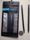
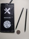
A flat head can scrape the silk screening off. I use these plastic spudgers .

Soak some small pieces of paper toweling with acetone and place on the glue for a little while, then the glue comes off a little easier.

IMG_20250116_084535308.jpgIMG_20250116_084542045.jpg
 
Thanks for the suggestions guys. I used acetone and carefully pushed away at the glue.

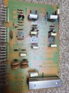
Yesterday's efforts:
 

Attachments

  • 20250216_142941.jpg
    20250216_142941.jpg
    212.8 KB · Views: 13
  • 20250216_142949.jpg
    20250216_142949.jpg
    236.2 KB · Views: 11
Another question please...

I am wanting to replace the resistors on this power board. Mostly, just the ones that are standing up off the board. Upon inspection, one resistor was already replaced with two in parallel (I think I can do better than this) and the others show signs of being hot. Seems like the right thing for me to do at this time.

I've found nothing as far as resistor replacements in the forum parts list for this power supply, and furthermore, when I search for the old part numbers (like PSF 272J), I don't see substitutes. So, I've taken to Mouser to search for resistors by resistance. I can find items, but there seems to be several choices.

Should I select the Carbon Film vs the Metal Oxide where specified, or it seems that maybe the Metal Oxide may be better (they seem to have a slightly higher wattage rating)?

Does the brand (manufacturer) matter?

Only R13 and R14 specify to use a 2 watt resistor. The remainder do not specify a wattage (only the resistance). Is it generally better to select a resistor with a higher wattage rating when given a choice for a selected resistance?

When reinstalling the new resistors, should I keep the 'insulators' in place? Not sure of the function these provide.

I do appreciate your guidance!

Scott
 
For the 2 watters stick with the metal oxide.

Higher wattage makes sense in some cases. Not always wise to randomly up the wattage rating.

A lot of power supply resistors are pushed rating wise in many supplies.

You can use metal or carbon films for the others.

I would use 1 watt rated resistors for the ones raised off the board. Re-use the lead spacers to keep them raised above the board.

This is just my thought on the tubes over the resistor bodies. I think they used them on the carbon film resistors to make them semi flame proof. They have to reduce the ability of the resistor to shed heat.

That said, this is my opinion if you use carbon films and they are not flameproof, put the tubes back on. If you use metal films get the flameproof types if you can and leave the tubes off, other wise use the tubes.

Look at the specs and pick ones that have the larger body size to better shed heat. Here is an example of a 1 watt large body carbon film: https://mou.sr/4iiuAAD
 
It might be important to know that when these units were new, many of us left them on CONSTANTLY! You can bet when this machine was new, the owner wasn't buying it to look at.
 
Back
Top Bottom