


I had a couple of SX-1980s come across the bench recently with USA made power supply boards. This is not the typical Canadian made board that is prevalent nowadays. This USA board has four aux heat sink mounted transistors that are detachable using the same headers found on modern McIntosh equipment. The quality is excellent and removable screw down headers make removal a breeze.
The problem is, there is an error in the 13.5V regulator circuit which causes terrible buzz in the background when using the tuner. The resistor circled in green in the image below (R202) is supposed to be 3.3 ohm if we are staying true to the original schematic. I received the original documentation for this board and was able to identify the error. The provided schematic shows R202 as 3.3K, the parts list shows it as 22 ohm. In my case, both units had 22 ohm loaded in this position.
The resistor found in the unit was a CPF322R000FKE14 - 22 ohm 3W Metal film. I replaced it with the same resistor type in 3.3 ohm.
Correct Part: CPF33R3000FKRE6
After replacement, the regulator circuit is much happier, clean 13.5VDC with no ripple. If you come across a unit with this board installed and have a buzzing or poorly functioning tuner, this is likely your issue.
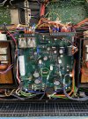
The problem is, there is an error in the 13.5V regulator circuit which causes terrible buzz in the background when using the tuner. The resistor circled in green in the image below (R202) is supposed to be 3.3 ohm if we are staying true to the original schematic. I received the original documentation for this board and was able to identify the error. The provided schematic shows R202 as 3.3K, the parts list shows it as 22 ohm. In my case, both units had 22 ohm loaded in this position.
The resistor found in the unit was a CPF322R000FKE14 - 22 ohm 3W Metal film. I replaced it with the same resistor type in 3.3 ohm.
Correct Part: CPF33R3000FKRE6
After replacement, the regulator circuit is much happier, clean 13.5VDC with no ripple. If you come across a unit with this board installed and have a buzzing or poorly functioning tuner, this is likely your issue.


