
• The move to the new server is done. There are some software and database maintenance updates in process. This has us passing the hat around to help out. We appreciate any donations. Seriously, even a dollar helps. The payment page may be found here - https://www.audiokarma.org/support.html

SX 3900. Bad transformer?

jFF_Bulbo

Active Member
hello everyone

I have a sx 3900 in which the DBT sends a short circuit when energizing,
the unit has been restored and in particular the amplification section has been rebuilt according to the recommendations of the forum.
The power transistors are the 2sc2922/2sa1216. and in particular the unit has the problem that the 2sa1216 and emitter resistors and some small 220 ohm resistors break down if the unit is powered at 120v.
Well, I've been racking my brains trying to fix it, but I noticed something that might be important.

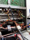
Between the +60V channel (red cable that feeds the power transistors from the source) and the chassis there is no continuity, however there is continuity between the -60v channel (orange cable) and ground, which makes me doubt about the good Main transformer status.

AWR-214
RECTIFIER ASSEMBLY
PIN 8-9 & CHASSIS NO CONTINUITY ON MULTIMETER
PIN 11-12 & CHASSIS CONTINUITY ON THE MULTIMETER
THE CONTINUITY WAS ALSO CHECKED IN BOTH CASES WITH PINS 13, 14 AND 15, WITH THE SAME RESULTS.
1689185753089.jpg

IS THIS A SIGN THAT THE TRANSFORMER IS BAD?
 
Register to hide this ad
does it change if you reverse the leads on the meter? There is a diode you have to read through.

If the transformer were bad, you wouldn't have normal rail voltage. If the +/- 60v is where it belongs the transformer isn't the issue.

did you confirm the transistors upstream of the outputs are good? Often when the outputs short, at least the stage before the outputs also fails.
 
¿Cambia si invierte los cables del medidor? Hay un diodo que tienes que leer.

Si el transformador fuera malo, no tendría un voltaje de riel normal. Si el +/- 60v es donde pertenece, el problema no es el transformador.

¿Confirmó que los transistores aguas arriba de las salidas están bien? A menudo, cuando las salidas se acortan, al menos la etapa anterior a las salidas también falla.
Hello, thanks for answering.
Yes, when inverting the cables in the diode test, it turned out as you describe.

Using the dbt, the voltage readings are +54v and +54v, so I'm assuming the transformer is fine.
power transistors are ok, tested one by one. the drivers that were originally 2sc2275/2sa985 have been replaced by 2sc5171/2sa1930.

I have changed the resistors of the emitters for an arrangement of double resistors

when the unit arrived, the left channel was bad. It was brought from the technician who tried to repair it without success. I did the repairs that I thought necessary but it kept throwing the fault, the 2sa1216 transistors were simply failing, so I decided to rebuild everything.

I have rebuilt the amplification circuit at least 3 times, capacitors, zener diodes, trimpots, all transistors according to what is recommended in the forum, but without success.
-if I disconnect the 4 2SA power transistors, everything is ok, dbt without short circuit

-If I leave the power transistors connected but I disconnect pins 1 or 5, where the source is fed with +54 and -54, everything is ok.

-leaving everything connected throws a short circuit in the dbt.

thanks for your help.
 
The initial settings of the three trim pots on a NSA amp are critical.

It sounds like you have the idle current set wayyy too high.

VR1 & VR2 are set as centered, to adjust terminals 30 & 29 each to 0.000v referenced to ground.

The manual has you set the 56 mv adjust pot (Vr3, Vr4) and the 70 mv adjust pot (vr5, vr6) fully counter clockwise.
That will give 0 ohms of 100 for vr3 & vr4.
That will give 0 ohms of 100,000 for vr5 & vr6

next adjust vr3 & vr4 to 56 mV then set vr5 & vr6 to 70mV.

after the unit thermally stabilizes, the idle current of 70 will probably be too high.
WHEN ADJUSTING IT DOWN:
go alll the way CCW on vr5 / vr6, then adjust the 56mV vr3 or vr4 pot to 56 again, THEN adjust vr5 & vr6 for 70mV.


be advised, the type of heat sink used in this unit is EXTREMELY dependent upon orientation and ventilation.
 
hello thank you.

when i connect all the wires (1 TO 8) on top of the pcb and all the jumpers in the bottom, bdt shine like the sun, relay in protection circuit engages, but relay on the amplifier doesn´t. the dial and all the light in front doesn´t work.
if i conect the unit to the 120v, 2sa output trasistors Will blow up, as far as some resisitors, maybe the drivers. it was happening the 3 times i rebuild the amplifier board.
 
You must limit the current to find the short, check voltages and don't ignore the pre-amp -- if you have high or low DC voltage going to the input on the amp board it's gonna blow up the outputs. Do not apply mains voltage until you get the short fixed.

Follow Mark's advice -- on this amp improper settings on the bias variable resistors or broken variable resistors can cause the outputs to fail, and you KNOW you have far too much current draw.
 
I think the idle trimmers work backwards from each other. CCW for the left and CW for the right, min resistance for a zero reading. I used two meters and blipped the DBT while watching the idles. I was able to get them situated for the start of the adjustment procedure.
Double check my thoughts.
 
I think the idle trimmers work backwards from each other. CCW for the left and CW for the right, min resistance for a zero reading. I used two meters and blipped the DBT while watching the idles. I was able to get them situated for the start of the adjustment procedure.
Double check my thoughts.
which is why I specify an OHMS reading. CCW and CW are an INTENT, but may not represent the reality of a board, nor of prior molestations work.

the 3900 AWH-097 pattern has the tap connected consistently across all six.
 
Last edited:
Back
Top Bottom